


How to Test a Capacitor With a Multimeter
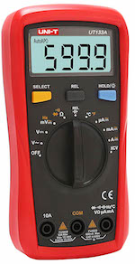
Figure 1: Multimeter
A multimeter is a versatile device used to measure voltage, current, resistance and perform other checks, like continuity and temperature, for electric circuits. These measurements are used for a wide range of applications, like checking a capacitor for possible faults. A multimeter can be used in numerous ways to check a bad capacitor, thereby troubleshooting the cause of error in an electronic board. See below for a complete guide on how to check a capacitor with a multimeter.
Table of contents
- Method 1: Use the capacitance mode on the multimeter
- Method 2: Use the Resistance (Ω) mode on the multimeter
- Method 3: Use a simple voltmeter to test a capacitor
- Method 4: Use the continuity mode of a multimeter to check the capacitor
- Method 5: Use the time constant parameter to check the capacitor
- Method 6: Check the capacitor visually for faults
- Method 7: Traditional method to check a capacitor
- FAQs
View our online selection of clamp meters and multimeters!

Method 1: Use the capacitance mode on the multimeter
Most digital multimeters come with an inherent mode to test the value of a capacitor, as shown in Figure 2 (note the symbol of capacitor). This is the most common method for testing a capacitor. A capacitor can be tested for its functionality directly by entering the capacitance mode in the multimeter and performing the following steps:
- Remove the capacitor to be tested from the electric board.
- Discharge the capacitor completely by connecting it across a resistor, and remove the capacitor thereafter for testing.
- Connect the capacitor terminals to the leads of the probe (positive terminal of the capacitor to the red probe and the negative terminal of the capacitor to the black probe of the multimeter). In a typical polar capacitor, the longer lead is the positive terminal, and the shorter lead is the negative terminal.
- Rotate the selection knob of the multimeter and select the capacitance mode.
- Note the value on the display panel and compare it with the value given on the capacitor case to check for any faults.
- Some fluctuation from the actual value is acceptable (typically within a tolerance band of 10-20 %), but if the displayed value is very high or very low compared to the actual value, the capacitor may be faulty and has to be replaced.
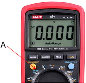
Figure 2: The capacitance mode (C) in a multimeter
Method 2: Use the Resistance (Ω) mode on the multimeter
A multimeter in resistance mode can be used to check if a capacitor is faulty or not. The basic principle used is the capability of a capacitor to charge when a current flows through its leads. To check a capacitor in the resistance mode, perform the following steps:
- Remove the capacitor to be tested from the electric board.
- Discharge the capacitor completely by connecting it across a resistor, and remove the capacitor thereafter for testing.
- Twist the selection knob and select a value in the OHM range, say 1kΩ.
- Connect the leads of the multimeter probes to the positive and negative terminals of the capacitor to be tested. Current flows through the capacitor, and the capacitor starts charging.
- In the case of a digital multimeter, a series of values will appear on the display panel, increasing in order and finally settling at infinity.
- If the displayed values rise from a very low value and progress towards infinity, it shows the charging action of the capacitor, ensuring that the capacitor works fine.
- A constant very low value displayed shows that the capacitor has a SHORT, and a constant very high value indicates that the capacitor is OPEN and may be replaced in both cases.
- In the case of an analog multimeter:
- If the needle points at a very low value and propagates towards a high value (showing the charging action of the capacitor), the capacitor functions well.
- If the needle is stuck at a very low value, there may be a SHORT in the capacitor, and if it is stuck at a very high value, the capacitor may be OPEN and needs to be replaced in both cases.
Method 3: Use a simple voltmeter to test a capacitor
To check a capacitor using the voltmeter functionality of a multimeter, perform the following steps:
- Note the maximum permissible voltage across the capacitor (35 volts as in the case of the capacitor in Figure 3).
- Charge the capacitor to a voltage that is less than the maximum voltage allowed through a voltage source (For example, 3 volts in the case of the capacitor shown in Figure 3 would work fine). Make sure to connect the battery positive terminal to the longer terminal of the capacitor and the negative terminal to the shorter terminal of the capacitor.
- Connect the capacitor leads to the probes of the multimeter (positive terminal to the red and negative terminal to the black probe, respectively).
- Shift the knob of the multimeter, and choose the DC voltage range. If the value displayed is the same as that of the voltage to which the capacitor is charged, the capacitor functions well, else it is faulty.
- The measurement has to be done fast, else the capacitor begins to discharge, giving a faulty reading on the multimeter.
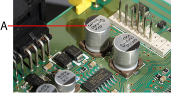
Figure 3: The voltage rating on a capacitor (A)
Method 4: Use the continuity mode of a multimeter to check the capacitor
A capacitor can be checked for continuity using a digital or analog multimeter by following the instructions given below:
- Remove the capacitor to be tested from the electric board.
- Discharge the capacitor completely by connecting it across a resistor, and remove the capacitor thereafter for testing.
- Connect the capacitor leads to the probes of the multimeter (positive terminal to the red and negative terminal to the black probe respectively).
- Twist the multimeter knob and select the option for continuity check (Select the symbol which shows a propagating wave).
- If the meter gives a continuous beep sound (or LED turns ON) there is a SHORT within the capacitor.
- If the meter doesn’t produce a beep sound, it means that the capacitor is OPEN.
- If the meter produces a beep sound at first (or turns the LED ON) and gradually stops, it indicates that the capacitor is in good condition.
Method 5: Use the time constant parameter to check the capacitor
The time constant of a circuit is the time taken by the capacitor to charge to 63.2% of the applied voltage through a known resistor and it is calculated by the formula: Τ=RC
Where:
- Τ: The time constant of the circuit commonly referred to with the greek letter tau
- R: Known resistance
- C: Capacitance value present in the circuit
For example, if a voltage of 10V is applied across the series combination of a resistor and a capacitor, the time constant is the time taken by the capacitance to charge to 63.2% of 10V, which is 6.32V. Use a stopwatch to measure the time taken by the capacitor to charge to this voltage (which is the time constant of the circuit). If the resistor value is 100 ohms, the equation for time constant can be used to derive the value of the capacitor used in the circuit.
To determine whether a capacitor is faulty or not using the time constant as a parameter, perform the following steps:
- Remove the capacitor to be tested from the electric board.
- Discharge the capacitor completely by connecting it across a resistor, and remove the capacitor thereafter for testing.
- Connect a known value of resistance in series with the capacitor.
- Connect the ends of the capacitor to the multimeter probes and set the knob to measure DC voltage.
- Apply a known voltage (For example, 10V) across the series connection.
- Note the voltage across the capacitor being displayed on the panel.
- Use a stopwatch to measure the time taken by the voltage to drop to 63.2 % of the applied voltage (in this case, 6.32V, as discussed earlier).
- Using the relation Τ=RC, calculate the value of capacitor manually using the value of time constant Τ and resistance R.
- Compare the experimental value of the capacitor with that of the printed value on the same capacitor. If both values are nearly the same, the capacitor is in good condition.
- If there is a noticeable difference between the experimental and printed values, the capacitor is faulty, and it is time to replace the piece.
Method 6: Check the capacitor visually for faults
A capacitor can be checked visually to look for apparent signs and determine if it is faulty or not. The capacitor is damaged in the following conditions:
The capacitor has a bulging top vent
During the failure of an electrolytic capacitor, the pressure is released through weak points at the top vent of the capacitor. This avoids damage to the surrounding components that are connected at proximity to the failed capacitor. During failure, the capacitor releases a gas pressure, causing an electrolytic discharge that breaks the top vent of the capacitor, which eventually causes the bulging top as seen in Figure 4.
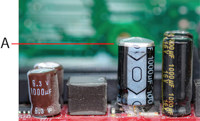
Figure 4: Capacitor with a bulging top vent (A)
The capacitor has a bulging bottom and lifted case
During the failure of a capacitor, if the released gas pressure does not break the top vent, it goes to the bottom, thereby pushing the rubber and causing the bulge, which also lifts the case.
Testing ceramic capacitors and surface-mount device (SMD)
The following signs on ceramic capacitors and SMD can be checked to determine if they are faulty or not:
- Broken terminals
- Burnt, damaged, or cracks in the casing
Method 7: Traditional method to check a capacitor
The traditional method of checking the capacitor involves risk to the components and the user. Hence, this method should be practiced only when the capacitor is to be checked on short notice, else it is always a safer option to go for one of the methods listed from 1-6.
To check a capacitor using the traditional method, perform the following steps:
- Discharge the capacitor properly using a resistor.
- Connect two separate leads to the ends of the capacitor.
- Connect the capacitor leads to a 230V AC supply (or 24 volt DC) for a very short period (roughly 1-5 seconds).
- Remove the voltage supply and short the ends of the capacitor.
- If it makes a strong spark, the capacitor is good for use.
- If the spark produced is feeble, or if there is no spark at all, the capacitor is faulty and it should be replaced.
Precautions to be taken while following the traditional method of checking a capacitor:
- Always wear safety goggles while trying out this method.
- Never connect a polar capacitor to an AC supply.
- To ensure proper safety, use a 12-24V DC for both polar and non-polar capacitors.
- It is a better practice to attach a resistor in series with the battery and capacitor positive terminals to avoid excessive current while charging the capacitor.
To learn more about multimeters, read our multimeter guide. Also, learn how to test a battery using a multimeter in our technical article.
FAQs
How to discharge a capacitor with a multimeter?
Touch the probes to the capacitor's terminals and wait for the reading to stabilize.
How to charge a capacitor with a multimeter?
Use a power supply that has been set to the desired voltage. Connect the power supply's positive lead to the capacitor's positive terminal and the negative lead to the capacitor's negative terminal.
What setting on a multimeter to test a capacitor?
The most common method is by setting the multimeter to capacitance mode.
How to test a bad capacitor?
Connect the multimeter probes to the capacitor and set it to capacitance mode. Then, take the value and compare it to the expected value of the capacitor. If it is within 10-20% it is good, if not, it is bad.