


Current Transformers
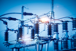
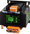
Figure 1: Current transformer
The electric power generated in a power plant is transferred through power lines and distribution systems to be consumed through residential applications. The current levels should be measured during the production and distribution to ensure that the optimum values are transferred at various points along the power distribution system. This current is often very high, which cannot be measured with a conventional ammeter. Specialized transformers known as instrument transformers measure very high voltage and current along the power system. The instrument transformer used to measure high current values is called a current transformer, and the one used to measure a high voltage is called a voltage transformer. This article discusses the construction and working principle, types, and applications of current transformers.
Table of contents
- What is a current transformer
- Current transformer construction and working
- Types of current transformers
- Working of current transformers
- Why a current transformer should not be kept open
- Difference between current transformer and voltage transformer
- Current transformer advantages and disadvantages
- Current transformer applications
- FAQs
View our online selection of transformers!

What is a current transformer
A current transformer is an instrument transformer that reduces high alternating currents in the primary winding to a low value in the secondary winding. This is primarily used when a current is too high to measure directly. Therefore, they provide a convenient way of safely monitoring the actual high-value alternating current flowing through a transmission line.
Current transformers have two basic functions:
- Adapting the medium voltage current value at the primary winding to a low current value at the secondary winding suitable for commercial metering devices and other residential applications.
- Isolating power electronic circuits from the metering or protection circuits. A current transformer acts as an intermediate device between the various electronic circuits and metering equipment. The current transformers provide isolation from the electric circuit’s high voltages and currents. These transformers provide a secondary current in the range 0-5A that is connected to the metering devices.
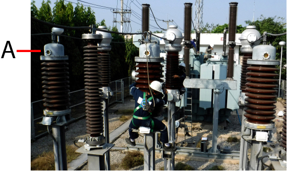
Figure 2: Current transformer (labeled A) in an electric substation
Current transformer construction and working
The construction of a current transformer is similar to that of a conventional transformer. The transformer is fundamentally a step-down transformer (with respect to current), consisting of primary and secondary windings without any electrical connection between them. The number of turns and the currents in the primary and secondary windings of a transformer is linked as:
N1 / N2 = I2 / I1
- N1: Number of turns in the primary winding
- N2: Number of turns in the secondary winding
- I2: Current flowing through the secondary winding
- I1: Current flowing through the primary winding

Figure 3: Current transformer symbol
To step down current to a very low value, the number of turns in the secondary should be larger than the number of turns in the primary (N2>N1). Therefore, the primary section of a current transformer is wound with a few turns of a conductor with a thick cross-section in the winding. The secondary section is wound with more number of turns of conductor with a small cross-section.
The primary winding (Figure 4 labeled A) and secondary winding (Figure 4 labeled C) are wound on a magnetic core made of silicon steel laminations (Figure 4 labeled B). According to Faraday's law of induction, the current flowing through the primary winding induces a magnetic field across the winding. A part of this magnetic field links with the secondary winding, thereby initiating a current flow in the secondary coil. The magnetic core provides a low reluctance path for the flow of the magnetic field created.
A current transformer used in a small line voltage system typically uses tape or varnish as the insulating material. In contrast, oil-immersed current transformers are used in a high-line voltage system.
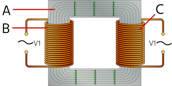
Figure 4: Rectangular core wound-type current transformer
The high-current carrying line (Figure 5 labeled C) supplies current to the load (Figure 5 labeled B). The primary side of the current transformer (Figure 5 labeled CT) is connected in series with the high-current line. The secondary side of the transformer is connected to a low-range ammeter (range 0-5A) that reads the current flowing through the secondary windings.
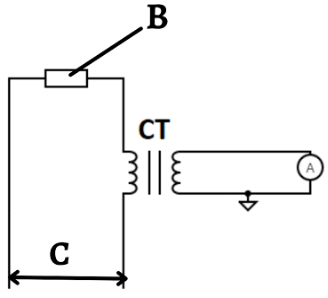
Figure 5: Connecting a current transformer for measuring current
Types of current transformers
Depending on the construction, there are two types of current transformers: wound-type and bar-type current transformers.
Wound-type current transformers
In a wound-type current transformer, both primary and secondary coils are wound on a core. The core can be in the shape of a rectangle or ring made up of steel or nickel alloy. A rectangle-shaped core is shown in Figure 4. In ring-type core transformers, the secondary section coil (Figure 6 labeled C) is wound on a ferromagnetic core (Figure 6 labeled A). The primary section coil (Figure 6 labeled B) is wound on the outer core with suitable insulation between both windings. Wound-type current transformers are cheaper than bar type, but are not as accurate.
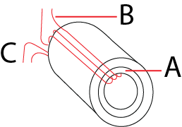
Figure 6: Ring-type core transformer
Bar type current transformer
A bar-type current transformer has no primary winding. The primary side consists of a bar-type conductor(Figure 7 labeled C). The secondary part consists of windings wound on a circular core surrounding the primary bar conductor (Figure 7 labeled B). A paper insulator is kept on the bar between the primary and secondary sections. The primary and secondary segments are tightly packed, and the distance between them is kept small to reduce flux leakage, thus enabling highly accurate measurements. A bar current transformer can withstand stresses of heavy overcurrent. This type of transformer is commonly found on installations where the voltage is 25kV or less. Bar-type transformers are costly compared to the wound-type counterparts, but give extremely accurate results due to reduced flux leakage.
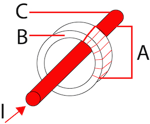
Figure 7: Bar type current transformers
Working of current transformers
The working of a current transformer is similar to that of a conventional two-winding transformer. A current transformer is used to measure high currents. When the high current flows through the primary winding of the current transformer, it induces a small current through the secondary depending on the number of turns in both windings. A low-range ammeter connected across the secondary can measure the current flowing through the secondary winding.
In a transformer:
N1 / N2 = V1 / V2 = I2 / I1
- N1: Number of turns in the primary winding
- N2: Number of turns in the secondary winding
- V1: Voltage through the primary winding
- V2: Voltage through the secondary winding
- I2: Current flowing through the secondary winding
- I1: Current flowing through the primary winding
Therefore knowing the number of turns in the primary and secondary windings, along with the value of secondary current measured using an ammeter, can be used to determine the high-value current flowing through the primary winding.
Example
Consider a current transformer having a turns ratio (N2/N1) of 300:1. If the ammeter reads 1A on the secondary side of the transformer:
- N1 = 1
- N2 = 300
- I2 = 1A
- Therefore, I1= (1/ 300) ✕ 1 = 300A
Also, note that since the voltage in the primary or secondary is directly proportional to the number of turns, the voltage induced in the secondary winding is 300 times that in the primary side. Hence, a current transformer acts as a step-up transformer with respect to voltage.
Why a current transformer should not be kept open
In a magnetic circuit, magnetomotive force (MMF) is the force responsible for the generation and motion of magnetic flux. When current flows through the primary windings, the MMF created in the primary side is N1 ✕ I1 (ampere-turns).
The MMF produced in the primary side leads to the production of magnetic flux that flows through the core, producing MMF and magnetic flux production in the secondary. The secondary side MMF is typically balanced by the MMF on the primary side. When a load is connected to the secondary winding, the current starts flowing in the winding, generating its own magnetic flux, which links with the primary winding. For example, the current flowing through the secondary winding increases if the load connected to the secondary side is decreased. This increases the flux on the secondary side, thereby increasing the net flux on the primary side through mutual induction. Hence, the magnetic flux in the primary and secondary sides remains the same.
If the secondary side of a current transformer is left open, the current through the secondary windings becomes zero; hence the MMF produced in the secondary, which generally balances the MMF produced in the primary winding, becomes zero. As there is no counter MMF, the unopposed primary MMF produces very high flux within the core leading to:
- Excessive core losses. Core loss is the energy loss within the core caused by an alternating magnetic flux. An unstable magnetic field eventually destroys the core material's functioning.
- Heating the coil beyond its limit
- Damage to the winding’s insulation
Also, the large secondary voltage may act as a safety hazard for the operators. Hence, it is a common practice to ground the secondary side to avoid the danger of electrocution to the operator.
Difference between current transformer and voltage transformer
Current transformers and voltage transformers are safe tools to measure high-valued currents and voltages with extreme accuracy. The difference between current transformers and voltage transformers is given in Table 1.
| Basis for comparison | Current Transformer | Voltage Transformer |
| Definition | Transforms high input current to a low output current | Transforms high input voltage to a low output voltage |
| Connection | Connected in series with the instrument | Connected in parallel with the instrument |
| Primary and secondary turns | Small number of primary turns compared to that of secondary winding | Large number of primary turns compared to that of secondary winding |
| Core Construction | Silicon steel lamination | Top-quality steel operating at low flux densities |
| Full line current/ voltage | The primary winding contains the full-line current | The primary winding contains the full-line voltage |
| Types | Wound type and bar-type | Electromagnetic and capacitive potential types |
| Open circuit at secondary side | A current transformer’s secondary winding cannot be left open. | A potential transformer’s secondary winding can be left open. |
| Applications | Current measurement and operating protective relay in the substation | Voltage measurement and operating protective relay in the substation |
Table 1: Difference between current transformer and voltage transformer
Current transformer advantages and disadvantages
Advantages
- Large currents can be measured safely.
- Isolates the high-current line from the measuring devices (like voltmeter and ammeter).
- Acts as a controlling device to operate protecting devices such as pilot lights and relays.
- A single current transformer can be fed to numerous instruments.
Disadvantages
- Measures only alternating current.
Current transformer applications
- Measuring current in commercial revenue metering applications.
- Protection device in high-voltage lines and electrical substations.
- Current converter applications in substations, and AC-DC filters.
- Used as an integrated protective module in capacitive banks.
- Used in handheld tools like AC clamp meters for current measurements.
FAQs
What is a current transformer used for?
A current transformer is used to measure the high current passing through a line, and also as an insulation device between power circuits and metering devices.
What is the difference between a voltage transformer and a current transformer?
A voltage transformer measures a high voltage and is connected in parallel across the line. A current transformer measures a high current and it is connected in series with the line to be measured.
Why is the current transformer referred to as a step-up transformer?
A current transformer converts a high current in the primary side to a low current in the secondary winding. The transformer steps up the voltage on the secondary side by reducing the current through the secondary windings.