


Globe Valves - A Comprehensive Guide
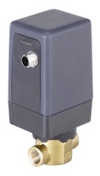
Figure 1: A Bürkert 2/2-way globe valve
A globe valve is a type of control valve that is used to modulate flow. Though a globe-shaped body is a typical characteristic of globe valves, they can come in a variety of shapes and sizes, depending on their design. A thorough understanding of how a globe valve works can help determine the right solution for each application.
Table of Contents
- What is a globe valve?
- How a globe valve works
- Globe valve design variations
- Manual vs automated globe valves
- How globe valves compare with other valve types
- Advantages and disadvantages of globe valves
- Choosing a globe valve for your application
- FAQs
View our online selection of globe valves!
What is a globe valve?
Initially characterized by their spherically shaped valve bodies, globe valves use a moveable plug or disc to control flow between the two separate chambers in the valve body. The disc moves in a linear direction as its actuator (handwheel or actuator such as in figure 1) rotates the stem lifting or lowering the plug or disc. This either allows flow, modulates the flow, or stops the flow through the orifice.
How a globe valve works
The exterior structure of a globe valve includes a valve body, handwheel, and bonnet. A threaded valve stem or screw connects to the handwheel and penetrates into the bonnet. On the interior end of the valve stem is a disc or plug, which can be a variety of shapes, depending on the application.
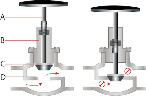
Figure 2: A globe valve in the open position (left), and in the closed position (right) with the valve stem (A), bonnet (B), disc or plug (C), and valve body (D).
There are five main components in a globe valve: valve body (Figure 2 labeled D), bonnet (Figure 2 labeled B), handwheel, stem (Figure 2 labeled A), and plug (Figure 2 labeled C). Media flows into the valve body through an inlet and exits the valve body through an outlet. The bonnet protects the threaded components of the valve and attaches to the valve body. As the user turns the handwheel, it turns the threaded stem, which in turn raises or lowers the plug. Raising the plug opens the orifice, allowing for media flow, while lowering the plug into the valve seat seals the orifice, preventing flow. Because this is a multi-turn valve, the handwheel must be turned multiple times to go from completely closed to fully open. However, a major benefit of this valve is its capacity to throttle or modulate flow by leaving it partially open.
Globe valves have a drawback known as head loss, also called pressure loss or friction loss. Head loss results from the turbulence caused by making the medium change directions twice as it passes through.
The amount of head loss created by a valve is measured using the L/D coefficient, which compares valves to a straight section of pipe. L stands for length and D stands for diameter. A valve with L/D=5 would create the same head loss as a pipe with the same L/D assuming all else is equal. For standard globe valves, straight ones have an L/D=~340 and a standard 90-degree globe valve has an L/D=~150. It is also important to measure your valve’s Kv & Cv value.
- Kv value: is an indication of the liquid or gas flow through a valve for a particular medium and pressure drop. Kv = Cv / 1.156.
- Cv value: is the flow-rate of water in gallons per minute at a temperature of 60 degrees Fahrenheit at a pressure drop of 1 psi. Cv = 1.156 x Kv.
Globe valve design variations
Globe valves come in a variety of shapes, or design variations, in order to lower the L/D coefficient of globe valves and reduce the amount of head loss. All three types stop or throttle the flow of fluids in the same manner, but each shape changes the flow path, affecting the amount of head loss.
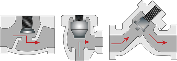
Figure 3: T- or Z globe valve (left), angle globe valve (middle), Y-globe valve (right)
T- or Z globe valve
The most common type of globe valve is t-shaped or z-shaped (figure 3 left). Though the 't-pattern' for the profile of the valve, 'z-shaped' is arguably more descriptive of how the fluid flows through the device. In the standard z-shaped globe valve, the water changes direction in a pattern that resembles the letter Z. These standard Z-shaped valves have the highest head loss, with an L/D=~340, but they provide a higher throttling capacity than Y-shaped or angle globe valves.
Y-globe valve
A Y-pattern globe valve (figure 3 right) is a modification of a t-pattern valve. Though fluid flow is in a straight line or 'z-pattern,' the bonnet and stem are placed at an angle relative to the valve body, forming a 'y-pattern' valve profile. By altering the position of the valve seat, there is a straighter flow path, resulting in a lower head loss. Y-pattern globe valves have a coefficient of L/D=~55, but they are less efficient at throttling flow.
Angle globe valve
An angle valve can act as both a valve and a pipe elbow because its inlet and outlet ports are at 90 degrees to each other. Because there is only a single change in fluid direction, this type of globe valve reduces head loss. The coefficient on angle globe valves is L/D=~150.
Manual vs automated globe valves
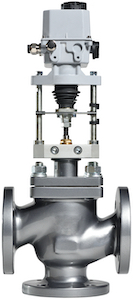
Figure 4: A pneumatic actuated globe valve
Manual actuation of globe valves is very common, but their primary use involves controlling flow, so they are excellent candidates for automation. With manual valve operation, turning the handwheel on the valve raises or lowers the threaded valve stem, but the handwheel can be replaced with an automated system using a pneumatic or an electric actuator.
Selection of the best actuator type for any application is dependent on whether you have compressed air or electrical power available to power the actuator, as well as the size of the valve, the installation environment, operational characteristics (fail-safe, cycle life, duty cycle, actuation speed, breakaway torque, need for manual override) and cost.
How globe valves compare with other valve types
Other multi-turn/linear motion valves and quarter turn/rotary valves are common valve classifications that are comparable to a globe valve. Their purpose and function determine how they are used in different applications.
Multi-turn/linear motion valves
Globe valves belong to the multi-turn/linear motion classification of valves because they use a multi-turn, threaded stem to move the valve disc in a linear direction. A gate valve also uses a multi-turn handwheel to move the valve plug in a linear direction, but a gate valve has a straight-through flow. The valve stem on a gate valve lowers a plug or obstruction that blocks the path of flow or allows flow without requiring the medium to change direction. Consequently, gate valves have a much lower head loss (L/D=~8) when fully open, but they shouldn’t be used to regulate flow due to a drastic increase in head loss and increased wear on the gate valve’s gate and seat.
Quarter turn/rotary valves
In contrast to globe valves and gate valves, quarter turn/rotary valves open and close using lateral movement rather than linear motion. In place of a handwheel, a rotary valve uses a wrench handle, moving only a quarter-turn (90 degrees) to open or close the valve. The cut-off valve on a gas line is a common example of this type of valve, designed for a quick on/off function.
Two common types of quarter turn/rotary valves are ball valves and butterfly valves, which differ in what is used to obstruct flow. Ball valves use a sphere, or ball, with a hole bored through it, allowing flow when the hole is parallel to the direction of flow and blocking it when in a perpendicular position. A butterfly valve uses a thin plate to block flow when its surface is perpendicular to the direction of flow or allow flow when parallel. Quarter turn/rotary valves have very low head loss (L/D=~3) but provide almost no throttling capability.
Advantages and disadvantages of globe valves
Globe valves come with several distinct advantages over other types of valves, such as:
- Shutoff
- Throttling
- Easy to maintain
- Disc replacement and seat resurfacing
The disadvantages of globe valves include:
- Head loss (can be reduced with Y-shaped globe valve or angle globe valve)
- Require greater force to seat the valve (automated actuators can provide assistance)
- Too slow for quick shutoff
Choosing a globe valve for your application
Globe valves provide the ideal solution in applications where flow needs to be modulated, but there is no concern about the amount of pressure loss, such as:
- Cooling water systems
- Fuel oil systems
- Feedwater and chemical feed systems
- Boiler and main steam vents and drains
- Turbine lube oil system
- Drain and trim applications in sprinkler systems (not as control valves in fire sprinkler systems, where pressure is at a premium)
Selection criteria
The criteria necessary for selecting the right globe valve for an application include:
- Choose the design that meets head loss and system configuration needs.
- Select the proper housing material to coordinate with the system.
- Choose the right seal materials and connections.
- Select a manual or automated actuator to meet the needs of a system.
- Ensure proper sizing to meet system requirements.
FAQs
What is a globe valve?
The globe valve affects closure or regulates flow using a disc with a flat or convex bottom lowered onto a matching horizontal seat located in the center of the valve.
How does a globe valve work?
Raising the valve disc using a threaded stem attached to a handwheel opens the valve, allowing fluid flow.
What are globe valves used for?
The globe valves are primarily used for on/off service of fluids as well as flow throttling applications.
Can a globe valve be automated?
As control valves, they are excellent candidates for automation. Automation choices include pneumatic pistons as well as diaphragm or electric rotary actuators acting directly on the stem to move the valve disc.