


Low Voltage Transformers
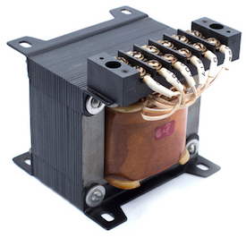
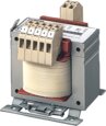
Figure 1: Low voltage transformer
A transformer is an electrical device designed to convert alternating current from one voltage to another. A low voltage transformer converts the main power supply voltage to a lower voltage, usually 12-15 volts. The efficiency of this voltage conversion governs how well the transformer controls the output voltage and the energy consumed in the process. This transformer is used in various applications like low-voltage landscape lighting systems as outdoor lighting transformers, and common household appliances. This article discusses a low voltage transformer’s operating voltage range, construction, working principle, applications, and typical ways to check for a transformer fault.
Table of contents
- What is a low voltage transformer
- Low voltage transformer purpose
- Working principle
- Low voltage transformer types
- How to test a low voltage transformer using a multimeter
- Installation
- Applications
- FAQs
View our online selection of transformers!
What is a low voltage transformer
A transformer is a vital power equipment for large-scale power plants and simple home circuits. A high voltage transformer is used in power plants and electric substations. A low voltage transformer steps down the input voltage to a low voltage at the output. A transformer installed within refrigerators and washing machines working on high voltage AC usually steps down the voltage to around 12 volts and is therefore categorized as a low voltage transformer. The main purpose of a low voltage transformer is to reduce the risk of electric shocks and short circuits to the user as these transformers are used in common household applications.
ANSI standard C84.1-1989 divides the operating voltage into the following categories:
- Low: < 600V
- Medium: 600V - 69kV
- High: 69kV - 230kV
- Extra high: 230kV - 1100kV
- Ultra-high: 1100kV
Depending on the operating voltage, a transformer falls in one of the five categories mentioned above. For example, a 12.8kV to 128 kV step-up transformer is a high voltage transformer, and a 230V to 14V step-down transformer is a low voltage transformer.
Low voltage transformer purpose
The main supply voltage (typically 120 volts in the US and 230 volts in countries in Europe) poses the danger of electrocution to a user if used directly. A low voltage transformer steps down the input voltage to a considerably low value, thus creating a safer environment for the user in commercial and residential structures. The normal value of voltage produced by a low voltage transformer is 12-24 volts, which does not generate heat under normal conditions. These low voltage conditions are safe enough to allow a person to install a light bulb even when the power is on.
Working principle
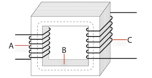
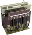
Figure 2: Construction of a low-power transformer showing primary windings (A), laminated core (B), and secondary windings (C).
A low voltage transformer works on the principle of induction, which states that a current-carrying conductor produces a magnetic field around it and vice-versa. As a low-power transformer converts the input voltage to a considerably low value, the number of turns in the secondary winding is much less compared to that in the primary winding.
A low voltage transformer consists of two sets of wires (see Figure 2):
- Primary winding (A): collects power
- Secondary winding (C): provides power
The primary and secondary windings are wound together on a magnetic iron circuit core, but these coils are not in contact with one another, as seen in Figure 2. The core is made of a soft magnetic material consisting of laminations (Figure 2 labeled C) linked together to help reduce core loss. Core loss is the energy loss within the core caused by an alternating magnetic flux. An unstable magnetic field eventually destroys the core material's functioning.
When the primary winding (Figure 2 labeled A) is connected to a power supply, current flows through the coil, and a magnetic field is induced. A part of this magnetic field links with the secondary windings (Figure 2 labeled C) by mutual induction, thereby producing a current flow and voltage at the secondary (load) side. The voltage produced at the load side is proportional to the number of turns in the secondary winding relative to that in the primary side. The voltage transformation is given by,
V1/V2=N1/N2
- V1: Voltage applied to the transformer primary winding
- V2: Voltage produced at the secondary (load) winding of the transformer
- N1: Number of turns in the primary winding
- N2: Number of turns in the secondary winding
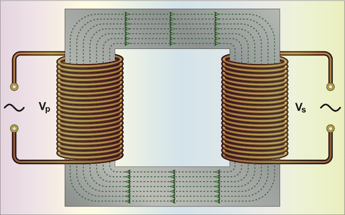
Figure 3: Magnetic lines produced within the current-carrying primary windings linking with the secondary windings.
Since a low voltage transformer produces significantly less voltage on the load side, the number of turns in the secondary winding is less than that in the primary. For example, to convert an AC main power supply of 120V to 12V, the number of turns in the primary winding should be ten times greater than that in the transformer’s secondary winding.
Note:The voltage and frequency of the main power supply vary from one country to the other. Countries like the USA use main power supply of 120 volts operating at 60 Hz, whereas those in Europe like the UK, Netherlands, and Germany operate at 230 volts and 50 Hz. See the complete list of countries with their corresponding mains power supply voltage and operating frequencies for more details.
Low voltage transformer types
Low voltage transformers are broadly classified into magnetic and electronic types.
Magnetic low voltage transformers (MLV)
The magnetic low voltage transformer is the most commonly used low voltage transformer type that uses two coils to reduce the mains power supply voltage to a considerably low value. The primary coil carries line voltage (typically 120 volts in the US and 230 volts around Europe). The current in the primary winding induces a magnetic field in the secondary winding.
Magnetic low voltage transformers are again classified into stack/laminated and toroidal types:
- Stack or laminated transformers: Stack/laminated transformers have sheets wrapped in copper wire laminated together to make a core (see Figure 2). These transformers have a long lifespan, approximately 15-20 years, but they are noisy and operate only at 80-85% efficiency.
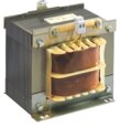
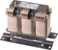
- Toroidal transformers: In a toroidal transformer, the primary and secondary coils are wound on a toroidal core, as shown in Figure 4. The unique and compact design of this transformer allows for shorter coils, thus reducing winding losses and improving overall efficiency. These transformers operate at 90-95% efficiency, have a life span of 20-25 years, and have quiet operation. But due to the difficulty of winding the conductor coils into the toroidal core, they are expensive. Also, these transformers are restricted to single-phase applications and have higher in-rush current.
Advantages of magnetic low voltage transformers
- Energy efficient
- Long life span of over 15 years
- Quiet operation
Disadvantages of magnetic low voltage transformers
- Huge size (in the case of laminated transformers)
- Expensive
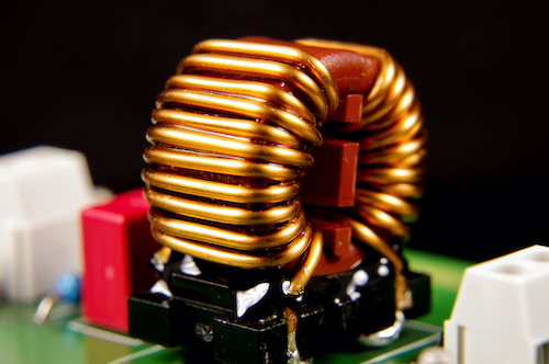
Figure 4:Toroidal transformer
Electronic low voltage transformers (ELV)
Electronic low voltage transformers have a more complex internal system consisting of circuitry paired with an inverter to accomplish the same functionality of magnetic low voltage transformers. The inverter increases the frequency of operation from ~50-60Hz to 20kHz or higher. The high frequency allows the use of a miniature core, thus enabling the transformer to be light and compact. These transformers are recommended for stepping down a voltage for indoor applications where space is a major concern.
Advantages of electronic low voltage transformers
- Compact size
- Less expensive
Disadvantages of electronic low voltage transformers
- High-frequency current may not be compatible with LED circuits
- Shorter lifespan of approximately 5-6 years
- Noisy and heat-sensitive
How to test a low voltage transformer using a multimeter
Symptoms of a defective transformer
Observe the appearance of the low-power transformer for the following abnormalities:
- Broken coil leads
- Rusted silicon steel sheet
- Burn marks on insulating material
- A loose fastening screw of the iron core
- Exposed winding coils
Also, a multimeter can be used to check a low-power transformer for possible faults.
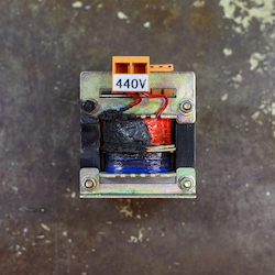
Figure 5: Burned transformer
Using a multimeter to check the no-load current of a low voltage transformer
No-load current is the current flowing through the primary winding of a practical transformer keeping the secondary side open (thereby creating a ‘no-load’ condition). The full-load current of a transformer is the maximum allowable current to the primary and secondary windings, and the value is typically used to design the transformer’s protection system. Perform the following steps to calculate the no-load current of a transformer using a multimeter:
- Open out the secondary windings of the transformer.
- Set the multimeter’s dial to measure current (AC).
- Connect the plugs of the transistor’s primary winding into the main power supply.
- Connect the leads of the multimeter probes to the ends of the transformer’s primary winding.
- The multimeter display indicates the no-load current value. The no-load current value should typically be not greater than 10-15% of the transformer’s full load current.
Example
A transformer is usually rated by its kVA (kilovolt ampere) value. A transformer rated at 5kVA delivers 5kW power to the load.
The full-load current of a single-phase transformer working at 230 V primary voltage and rated at 25kVA is (25✕1000)/230 = 108.7A. To determine whether a transformer works properly, check whether the measured no-load current is less than 15% of the full-load current.
Using a multimeter to check the continuity of a low voltage transformer
A continuity test can be performed on a low voltage transformer to check whether there is a break in the primary or secondary windings.
- Disconnect the transformer completely and set the multimeter to measure resistance(Ω).
- Connect the leads of the multimeter probes to the ends of the transformer’s primary winding and note the resistance indicated on the multimeter display. Very high or infinite resistance indicates a break in the primary side of the circuit.
- Connect the leads of the multimeter probes to the ends of the transformer’s secondary winding and note the resistance indicated on the multimeter display. Very high or infinite resistance indicates a break in the secondary side of the circuit.
- If the primary or secondary coils register an infinite resistance, the transformer must be replaced.
Note: A digital multimeter (DMM) displays an infinite resistance by OL (open line) on the screen.
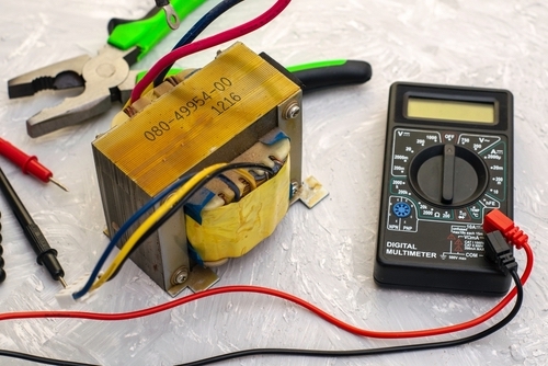
Figure 6: Checking a low voltage transformer with a multimeter
Applications
Typical applications involving a low power transformer are the following:
- A low-power transformer can be used as a low voltage lighting transformer in landscape lighting that works on 12-24 volts. The outdoor lighting transformer steps down the line voltage of 110 volts or 230 volts to a low value suitable for connecting lights to the voltage.
- Rectifiers utilize low-power transformers for stepping down AC main voltage to a low value which is converted to DC voltage using a combination of diode and capacitor.
- Common household appliances like refrigerators, washing machines, mobile phone chargers, thermostats, and doorbells use low-power transformers that produce a very low load voltage, thus protecting the user from electric shock and short circuits.
FAQs
How many lights can you connect to a low voltage transformer?
It depends on the maximum current draw from the transformer and the total wattage of the lights. For example, a transformer producing 300 watts can be connected to 300 lights of 1 watt or six lights of 50 watts. Ensure not to connect components to more than 80 percent of the transformer’s rated wattage for proper operation.
How long do low voltage transformers last?
Magnetic low voltage transformers run for a very long time, approximately 15-20 years, whereas electronic low voltage transformers run for 5-6 years.