


Solenoid Valve Parts
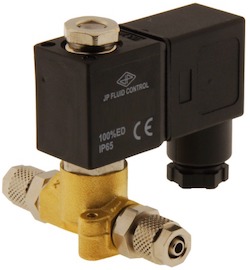
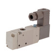
Figure 1: Solenoid valve
A solenoid valve is an electrically controlled valve that shuts off or allows fluid flow from one point to the other. The valve consists of two main components: a solenoid and a valve body. Within these components are various parts, and understanding them helps enhance the knowledge of how the valve works as a whole unit. This article discusses the multiple parts of the most common solenoid valve type, a 2/2-way valve, and its respective functions.
Table of contents
View our online selection of solenoid valves and buy one today!
What is a solenoid valve
A solenoid valve is an electromagnetically operated valve that allows engineers to autonomously and remotely control the fluid flow within a system. This valve is used to close, open, mix, or divert liquid and gaseous media in industrial and domestic applications. Solenoid valves have a faster response time and lower power consumption compared to other valve types. The power consumption can be reduced further by using a latching solenoid valve.
The various classifications of a solenoid valve are:
- Direct-acting and pilot-operated solenoid valves: Direct-acting solenoid valves directly connect with the opening and closing armature, whereas indirect acting solenoid valves (also called servo-operated or pilot operated) use the medium’s pressure difference across the valve ports to open and close the valve.
- Normally closed and normally open solenoid valves: A normally-open valve is open, and a normally-closed valve is closed in the de-energized state.
- 2-way and 3-way solenoid valves: Depending on the circuit function, solenoid valves can be 2-way, 3-way, 5-way, 7-way, etc. For example, A 2-way solenoid valve has two ports, namely an inlet and an outlet. Similarly, a 3-way valve (3/2 valve) has three connection ports. Typically, it has two states or positions it can be in, enabling the valve to switch between two different circuits. Read solenoid valve selection guide article for more details on the solenoid valve’s circuit functions.
- AC and DC solenoid valves: Solenoid valves can work on AC or DC power supply. Read our article on AC or DC solenoid valves for more information.
Solenoid valve parts
The different parts of a solenoid valve work together to ensure the optimal operation of the valve. Proper care must be taken to ensure that the parts are installed correctly. Missing or incorrectly installed components can cause a valve to malfunction. Read our article on solenoid valve installation for more information on the installation procedure. The main components of a 2/2-way solenoid valve are shown in Figure 2 and discussed below.
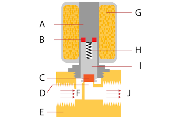
Figure 2: 2/2-way solenoid valve parts: armature tube (A), shading rings (B), seal (C), orifice (D), valve body (E), inlet port (F), solenoid coil (G), spring (H), plunger (I), and outlet port (J).
Inlet port (A)
The media enters the valve through the inlet port, after which it encounters the closing or opening functions of the valve. The media to be controlled enters the valve through a pipe or hose connected to the valve’s inlet port.
Outlet port (B)
The regulated fluid flows out of the valve through the output port. The output port receives the media that has been allowed to flow through the valve. A solenoid valve can have one or more outlet ports depending on the application. The valve media can be directed to one or more of these ports by the specific action of the valve. The regulated media leaves the valve through the pipe connected to the output port. Read our humidifier solenoid valve article for more details on how the pipes are connected to the inlet and outlet ports of a solenoid valve.
Solenoid coil (C)
The solenoid coil consists of several turns of enameled wire, taking a cylindrical shape and hollow from the inside. When current flows through the coil, a corresponding magnetic field is produced. The body of the coil is covered with steel and has a metallic finish.
Spring (D) and plunger (E)
The plunger, or piston, is the part of the valve that moves up and down to close or open the valve. The plunger is usually cylindrical in shape and made of a ferromagnetic material situated within the hollow space of the solenoid coil. The solenoid spring provides the force required to keep the plunger in its position. In a normally closed valve, the spring exerts pressure on the plunger, thus pushing it down and closing the seal. In a normally open valve, the spring holds the plunger up so that the valve remains open in its resting position.
For a normally closed solenoid valve, when the coil of the solenoid is energized by passing a current, it produces a magnetic field that attracts the magnetic plunger upwards (since the plunger is made of a ferromagnetic material), overcoming the force of the spring. As the plunger moves, the valve is opened, just as if it was opened by an operator moving a handwheel or a lever on the valve. Depending on the action required and the valve’s working mechanism, the plunger movement controls the flow of media through the valve. It may allow the fluid to pass, block, or regulate the amount that passes through. A normally open solenoid valve works in the opposite way (i.e. energizing the solenoid closes the valve).
Armature tube (F)
An Amature tube is a hollow component that acts as a guide for the plunger. Any flaws in the tube can restrict the motion of the plunger. The accumulation of dirt can also affect the movement of the plunger, causing heat and leading to valve damage.
Seal (G)
The seal is the part that shuts off the valve preventing the flow of media through the valve. The plunger moves up in a normally closed valve as the valve is energized. The seal opens the orifice and allows the media to flow through the valve. If the valve is normally open, the plunger moves down, causing the seal to block the orifice, thereby preventing the flow of the media through the valve.
The seal comes in contact with the medium to be controlled. Therefore, it is crucial to ensure that the seal material is compatible with the chosen valve media. Also, the seal should be kept free from dirt to prevent the partial opening and closing of the valve. Read our article on solenoid valve seal material for more information.
Orifice (H)
The orifice connects the inlet and outlet ports. The plunger operates this orifice, restricting the flow of media in and out of the valve. A solenoid valve can have one or more orifices depending on the working principle employed and the required action.
Shading rings (I)
The shading rings prevent vibration and humming in AC coils in a solenoid valve. Read our article on understanding solenoid design and function for more details on the importance of shading rings in AC solenoid valves.
Valve body (J)
The solenoid assembly is connected to the valve body. The valve body connects to the circuit that carries the fluid to be regulated. There are two openings in the valve body known as inlet and outlet ports. Valve manufacturers use high-grade materials for making the valve body as this part carries the media involved and should be capable enough to carry without fail. Valve bodies are constructed from different types of materials. The material is chosen according to its suitability to handle the media flowing through the valve and its characteristics, such as its ability to cause corrosion. Specific material options for the valve bodies of solenoid valves include stainless steel, plastic, or brass.
The design of the valve body varies between different solenoid valve types.
- Indirect (pilot) operated solenoid valves: In indirect operated solenoid valves, a membrane or diaphragm (as seen in Figure 3) separates the outlet and inlet ports from each other. The diaphragm closes and opens the valve’s main orifice from the action of pressure differences of the medium over the valve’s inlet and outlet ports, as seen in Figure 3. As the diaphragm is a moving part, it should be kept clean for the valve to operate correctly. The diaphragm divides the valve body into a lower and upper chamber. A small hole within the diaphragm allows the upper chamber to fill with fluid from the lower chamber and equalizes the pressure between chambers.
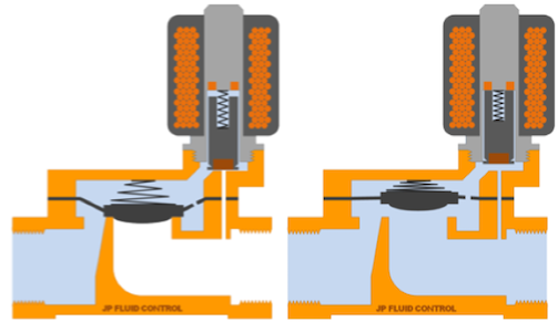
Figure 3: Pilot-operated solenoid valve working principle
- Semi-directed operated solenoid valves: These valves have a valve body design that includes an upper chamber and a lower chamber which are separated by a diaphragm or membrane, as seen in Figure 4. The membrane contains a small opening that allows the fluid to fill the upper chamber and equalize pressure. The solenoid plunger in a semi-direct operated solenoid valve is attached to the diaphragm; hence the plunger controls the diaphragm position directly, contrary to using a pilot to control the fluid in the upper chamber as seen in the case with the indirect-operated valve. Read our solenoid valve overview article for more information about the working of a pilot-operated and semi-direct operated solenoid valves.
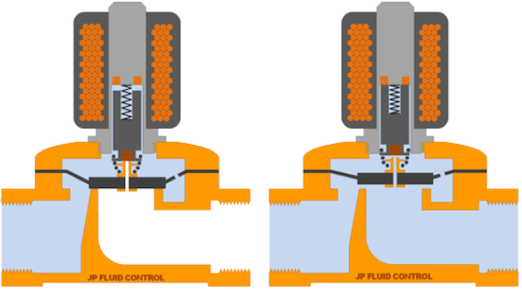
Figure 4: Semi-direct operated solenoid valves in closed (Left) and open states (Right)
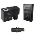
Lead wires
The lead wires (Figure 3 labeled W) connect the valve externally to the power supply directly or through a connector when the valve is energized. The current flow stops when the power is switched off.
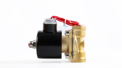
Figure 5: Lead wires in a solenoid valve
FAQs
What is a 2-way solenoid valve?
A 2-way solenoid valve has two connections, namely an inlet port and an outlet port. The fluid enters the inlet port and gets released through the outlet port.
What is a plunger in a solenoid valve?
A solenoid plunger, commonly called a piston, moves up and down to open or close the valve.
What is a solenoid valve used for?
A solenoid valve is an electrically controlled valve used to release, shut off, distribute or mix fluids in common industrial applications.