


What Is a Circuit Breaker
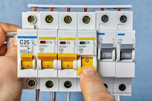
Figure 1: A tripped circuit breaker in a circuit breaker panel.
A circuit breaker automatically interrupts the flow of current in an electrical circuit in the event of an over-current or short-circuit. It prevents electrical fires and damage to electrical equipment. They are found in homes, commercial buildings, and industrial settings andcome in various sizes and types to meet the specific needs of different electrical systems. This article discusses the construction, working, and types of circuit breakers.
Table of contents
- What does a circuit breaker do
- How does a circuit breaker work
- Circuit breaker switching
- Circuit breaker types
- FAQs
View our online selection of circuit breakers!
What does a circuit breaker do
The electrical service panel, or circuit breaker panel, in a building contains a series of lever-operated circuit breakers. A circuit breaker’s size is determined by the amperage it is designed to trip at. When that amperage limit is exceeded, the circuit breaker trips to protect against fire and electrical hazards. Figure 1 shows a circuit breaker being turned on after it has tripped due to overload.
The most frequent causes of circuit breaker trips are:
- Overloading: This occurs when too much current is drawn from a circuit, for example, when multiple high-power devices are used simultaneously.
- Short circuits: Short circuit occurs when there is a problem with the wiring of an appliance leading to excessive current flow.
- Ground faults: Ground faults happen in areas with high moisture, such as kitchens and bathrooms. Ground Fault Circuit Interrupters (GFCIs) are now required by electrical code for safety.

Figure 2: Circuit breaker symbol. It is usually found in electrical schematics, wiring diagrams, and electrical engineering drawings.
How does a circuit breaker work
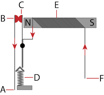
Figure 3: Circuit breaker construction: current line into the building/appliance (A), fixed contact (B), movable contact (C), spring (D), tripping coil wound around an electromagnet (E), and wire carrying the main or incoming current (F).
Figure 3 shows a schematic of how a circuit breaker connects the incoming live wire (F) to the current line running into the appliance (A).
- A circuit breaker consists of two contacts: one is fixed (B), and the other is movable (C).
- The contacts are placed in a closed chamber containing a fluid medium that quenches the arc formed (discussed in the next section) between the contacts.
- The contacts remain connected under normal operating conditions and do not open automatically unless there is a fault or current surge in the line.
- When the line experiences an overcurrent, the relay sends a signal that energizes the trip coils wound across an electromagnet (E).
- The trip coil is calibrated to activate when the current passing through it exceeds the set trip current. The resulting force pulls the contacts apart, creating an interruption in the connection between the live wire and the appliance. This mechanical process operates like a ratchet, maintaining the separation until manually reset. The contacts can be reset either directly or through a remote controller.
- A deformed metal spring (D) stores potential energy in the circuit breaker. When the tripping coil gets activated, the potential energy is released, causing the moving contact to slide at a speed. Compressed air or hydraulic pressure can also be used in place of the spring.
Arc in a circuit breaker
An arc is caused (Figure 4) when electrons jump across the narrow gap between contacts as they are separating. This ionizes the medium, reducing its resistance and eventually resulting in the flow of sustained currents. The phenomenon is particularly significant with high currents, and the circuit breakers designed for heavy industrial use are called contactors and are designed to separate very quickly to break the arc. An arc is dangerous because it delays the breaking of the circuit and generates heavy heat, which can cause damage.
Therefore, the main problem in a circuit breaker is to extinguish the arc within the shortest possible time by adopting suitable methods.
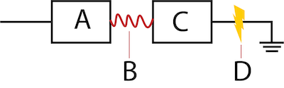
Figure 4: Arc formation in a circuit breaker: moving contact (A), arc (B), fixed contact (D), and fault (D).
Circuit breaker switching
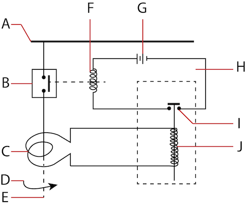
Figure 5: Circuit breaker working: busbar (A), circuit breaker (B), current transformer (C), fault (D), the circuit to be protected (E), trip coil (F), battery (G), trip circuit (H), relay contact (I), and relay coil (J).
Figure 5 shows the working of a circuit breaker (B) in an electric circuit. The two vital parts in the circuit are a current transformer (C) and a relay coil (J).
- Current transformer: A current transformer is an instrument transformer that reduces high alternating currents in the primary winding to a low value in the secondary winding. The purpose of this reduction is to make the current easier to measure and manage, especially when working with high-powered electrical systems. The primary windings of the current transformer are connected to the line to be protected, and the secondary winding is connected to the relay coil.
-
Relay coil: A relay is an electrically operated switch that opens or closes a circuit in response to an electrical input signal. It consists of an electromagnet that, when energized, attracts a metal armature to close a set of electrical contacts. This allows a current to flow through the relay, thus completing a circuit.
- The current at which a relay switches (also known as the pick-up current or trip current) is determined by the design of the relay and the coil used.
- The trip current is directly proportional to the magnetic field strength generated by the coil and is influenced by factors such as the number of turns in the coil, the wire diameter, and the magnetic core material.
If there is a fault (like overcurrent):
- There will be a high current in the incoming line.
- The current in the secondary of the current transformer increases, which is the current through the relay coil.
- The relay contact (I) will close under the high fault current.
- This closes the trip circuit of the circuit breaker, and current starts flowing from the battery (G), through the trip coil (F), in a trip circuit (H).
- The trip coil of the circuit breaker gets energized. This activates the circuit breaker’s opening mechanism, pulling the contacts apart.
- This isolates the faulty part from the rest of the line.
Circuit breaker types
Low voltage circuit breakers
Low voltage (LV) circuit breakers handle voltages up to 1 kV.
Miniature Circuit Breakers (MCBs)
Miniature circuit breakers are used for protecting circuits where current ratings are lower. They can be used up to 125A circuits. They are inexpensive, compact, and easy to install.
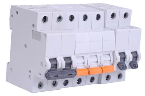
Figure 6: Miniature circuit breakers (MCBs)
Molded Case Circuit Breakers (MCCBs)
- A molded case is used to enclose the circuit breaker. These are large circuit breakers designed for high-voltage electrical systems.
- MCCBs are commonly used for current ratings up to 1600A and fault levels up to 150 KA.
- These circuit breakers are more durable and can handle higher current levels than MCBs.
- MCCBs operate using bimetal and solenoid components, but more recently, microprocessor-based MCCBs have become popular due to their quick, electronic-based release mechanism.
- MCBs and MCCBs are available in different configurations, such as single-pole, two-pole, and three-pole, to meet different electrical requirements.
- One of the main advantages of MCCBs is their high durability. They are commonly used as industrial circuit breakers in harsh environments where high current levels and roughconditions are common.
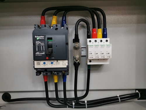
Figure 7: Molded case circuit breakers (MCCBs)
Air circuit breakers (ACBs)
These are high-voltage circuit breakers that use air to insulate the contacts and interrupt the current flow through the circuit breaker. They are ideal for use in industrial and commercial applications, where high current levels are common. ACBs are typically used for circuits handling currents up to 6300A.
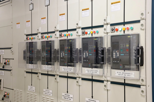
Figure 8: Air circuit breakers (ACBs)
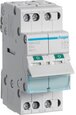
Residual current circuit breaker (RCCB)
A residual current circuit breaker (RCCB) is designed to offer protection against earth leakage. These breakers are utilized in homes, offices, and industries depending on the specific current sensitivity requirements for each application. In the event of a current leakage, the RCCB is designed to detect the issue and trip, thus preventing potential electrical shocks and other negative effects from the current leakage.
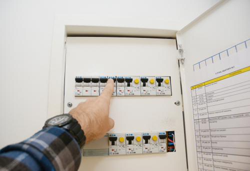
Figure 9: Residual current circuit breaker (RCCB)
Medium and high voltage circuit breakers
Circuit breakers that operate in the voltage range of 1 KV to 69 KV are classified as medium voltage circuit breakers. Those operating in the voltage range of 69 KV to 230 KV are referred to as high voltage circuit breakers. They are used in high-voltage power distribution systems, such as power transformers and substations.
Vacuum circuit breakers (VCBs)
- These are medium-voltage circuit breakers that use a vacuum as an arc-quenching medium.
- Vacuum circuit breakers have a long service life and are highly reliable due to the absence of moving parts in the breaker.
- They are compact, require minimal maintenance, and provide noiseless operation.
- They are used in the control rooms of grid stations.
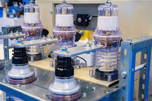
Figure 10: Vacuum circuit breakers (VCBs)
SF6 circuit breakers
- SF6 circuit breakers use SF6 gas as the medium for arc extinction, and it is highly effective in breaking contacts.
- The use of SF6 gas as an insulating medium allows circuit breakers to provide superior performance, reliability, and safety compared to other types of circuit breakers.
- SF6 gas has a high dielectric strength, making it suitable for use in high-voltage applications.
- SF6 circuit breakers have simple construction, minimal maintenance, and excellent arc extinction. Also, the same gas is recirculated through the circuit making the system more efficient.
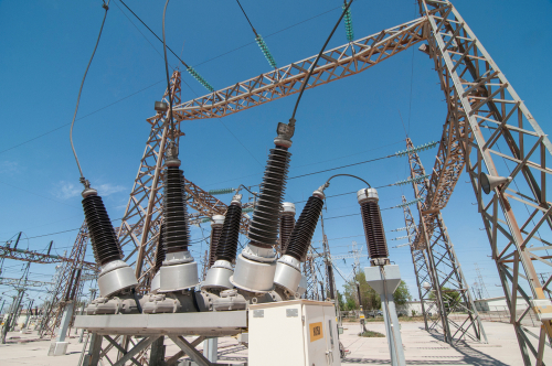
Figure 11: SF6 circuit breakers
Oil circuit breakers
- Used in high voltage systems.
- They employ oil as the medium for breaking the circuit during an overloading or short-circuiting event.
- They have a high short-circuit breaking capacity, making them suitable for use in high-voltage applications.
- Oil circuit breakers are prone to oil leakage and fire risk as the oil can form an explosive mixture with air. Also, it requires more maintenance as the oil has to be replaced frequently.
FAQs
Why does a circuit breaker trip?
A circuit breaker trips to interrupt the flow of electricity in an electrical circuit as a safety measure to prevent overloading or short-circuiting.
What are the different residential circuit breaker types?
Residential buildings use MCBs, MCCBs, GFCI, and arc fault circuit interrupters.
What is a solid-state circuit breaker?
A solid-state circuit breaker uses solid-state devices like diodes, thyristors, and transistors to control the flow of electricity instead of traditional mechanical components to interrupt the flow of electrical current in an electrical circuit.
