Valves Used in Reverse Osmosis Systems
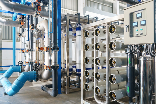
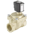
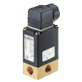
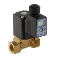
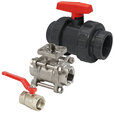
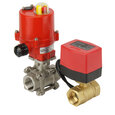
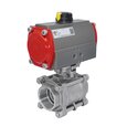
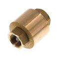
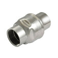
Figure 1: Reverse osmosis valves
Reverse osmosis (RO) is the process of water purification by which water under pressure is passed through a semipermeable membrane to remove contaminants, ions, large particles, and other impurities. For a reverse osmosis system to operate properly, a wide variety of valves are used in the application. This article examines how a reverse osmosis system functions and highlights the importance of valves in ensuring these systems operate effectively.
Osmosis
Osmosis naturally occurs when two solutions of different solute concentration are separated by a semipermeable membrane. This membrane is a material that allows certain sized molecules to pass through it. A simple example of this is a semipermeable membrane that allows water molecules to pass through but does not allow salt molecules.
The U-shaped tube in Figure 2 (left) has two solutions that are separated by a semipermeable membrane. There is fresh water with a low salt concentration (solvent) on one side and salt water with a high salt concentration (solute) on the other side of the membrane. The water with lower salt concentration will begin to move towards the side with higher salt concentration because nature strives for an equilibrium of free solvent molecules. This causes the water level on the side with higher salt concentration to rise. It is ‘pushed’ up by the purer water until osmotic pressure is high enough. Osmotic pressure is the pressure needed to prevent osmosis of solvent molecules across the membrane.
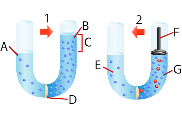
Figure 2: Osmosis (1) and reverse osmosis (2): Water (A), concentrated solution (B), osmotic pressure (C), semipermeable membrane (D), fresh water (E), external pressure (F), and seawater (G).
Reverse osmosis
As mentioned, reverse osmosis is ‘osmosis in reverse;’ it is not a natural process. Hence, for reverse osmosis to occur, pressure needs to be applied to the solution with the higher solute concentration.. This leads to the passage of water molecules through a semipermeable membrane towards the lower solute concentration region. This pressure should be higher than the natural osmotic pressure in order for pure water to pass through, leaving behind a solution with primarily contaminants or salts.
Figure 2 (right) shows a U-shaped tube with reverse osmosis in action. The applied pressure on the higher salt concentration water leads to water molecules moving across the membrane, thereby purifying water.
Reverse osmosis systems
A simple reverse osmosis system consists of a high-pressure pump (Figure 3 labeled B) which increases the pressure of feed water with salts, ions, or impurities (Figure 3 labeled A). This forces the water across a semipermeable RO (Reverse Osmosis) membrane (Figure 3 labeled C), leaving behind all the dissolved salts. The required pressure is directly proportional to the salt concentration of the feed water.
The RO membrane lets the cleaner water, called permeate water, through (Figure 3 labeled E). The salts and other contaminants stopped by the membrane come out as a reject stream (Figure 3 labeled D). This can be drained out or, if possible, recycled through the RO system to save water. RO systems remove up to 99% of dissolved salts (ions), particles, pathogens, and bacteria from feed water.
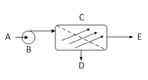
Figure 3: A simple reverse osmosis system: feed water (A), high-pressure pump (B), RO membrane (C), reject stream (D), and clean water (E).
Reverse osmosis valve types
Solenoid valve for RO water purifier
Normally solenoid valves for RO water purifiers are of 2/2 way (1 inlet, 1 outlet of the open/closed type), ideal for water ON/OFF control. There are three types of solenoid valves:
Direct operated fluid solenoid valves
Direct-acting solenoid valves have a compact design. As seen in Figure 4, the solenoid valve plunger rests directly over the flow path or orifice and controls the on/off function of the solenoid valve. As it does not use a membrane, the flow is restricted according to the orifice size.
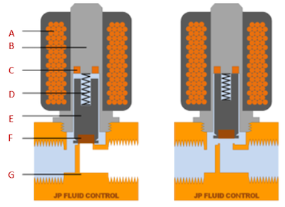
Figure 4: Schematic representation of a direct operated solenoid valve (2/2-way, normally closed) and components: coil (A), armature (B), shading ring (C), spring (D), plunger (E), seal (F), valve body (G)
Normally this is between 1mm to 5mm. As this type of valve is direct acting, it does not depend on system pressure differences to function. This makes it ideal for low flow, small, medium, and high-pressure systems up to 150 bar. Port sizes range from 1/8” to 3/8”.
Semi-direct operated solenoid valves
Semi-direct design uses a hung membrane and is pilot operated as shown in Figure 5. The internal solenoid valve membrane is attached or hung from the plunger assembly. The energized plunger thereby lifts the membrane and keeps it open mechanically. At the same time, the plunger opens a pilot orifice. As a consequence, the pressure of the medium supports the opening of the membrane. Hence, this type of solenoid valve operates without a pressure differential between the inlet and outlet. It is ideal for low pressure, closed loop, gravity fed, and water suction systems.
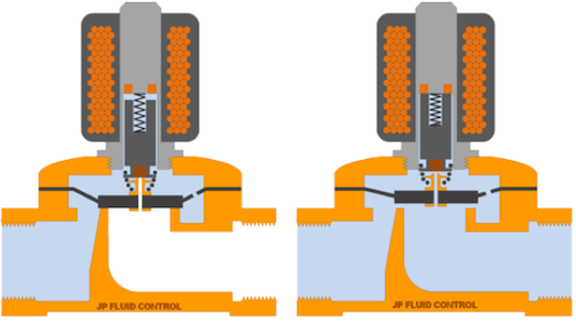
Figure 5: Schematic representation of a semi-direct operated solenoid valve (2/2-way, normally closed)
Indirect operated solenoid valves
Indirect solenoid valves (Figure 6) use a membrane that is not attached to the solenoid plunger. Hence, the membrane remains floating and uses a pressure differential between inlet and outlet to operate. This pressure differential is controlled by a solenoid actuated pilot circuit. The solenoid coil/plunger is mounted over the outlet channel port which connects the outlet and the area above the membrane. When energized, the pressure above the membrane is released into the outlet port via this pilot channel. This causes a pressure differential which lifts the membrane and allows medium to flow through the valve. When the pilot circuit is closed, the inlet pressure builds up above the membrane forcing it to close and stop flow of the medium.
It is ideal for medium to high pressure, open to atmosphere, and pump fed systems.
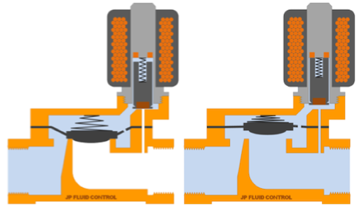
Figure 6: Schematic representation of an indirect operated solenoid valve (2/2-way, normally closed)
Check valves
Reverse osmosis check valves are connected to the water tubes of the RO membrane or the permeate outlet port of the membrane housing. These valves prevent backflow to the membrane. When there is back pressure in the system, for example when the tank is full, the spring-operated valve is engaged and stops the flow of water. Flow is not resumed until the back pressure drops below the feed pressure. These valves are required for systems operating with pressurized tanks and/or automatic shut off valves.
Feed valves
Feed valves are used to control the supply of feed water to RO systems. They have an ON/OFF function. Often, they are solenoid valves. They are offered in various styles and suitable for many plumbing scenarios.
Ball Valves
Two-way ball valves shut off the flow of water to and from equipment with a quarter turn of the handle. These valves can be manually, pneumatically, or electrically actuated. They can be used in intermediate positions to stop water flow to a system, tank, or components for easier servicing and extended non-use periods. Depending on the material, they are usually more robust than solenoid valves.
Automatic shutoff valves
Automatic shutoff valves shut off or turn on depending on the tank levels. These are membrane operated valves which work in conjunction with pre pressurized tanks. They also work with float valves to automatically turn the feed to the RO-system off when the tank is full and back on when the tank level drops below a certain pre-set point. They help to save and conserve water. They operate mechanically and no electricity is required.
Float valves
Float valves have a float that senses the water level in a tank or reservoir and automatically stops the flow of water into the tank or reservoir when the water level rises beyond a certain point. When the water level reaches the float position, the float’s buoyancy causes the valve’s arm to elevate, thereby closing the valve. When used in conjunction with a membrane type automatic shut off valve, the back pressure created by closing the tank valve will trigger the shutoff valve to turn off the feed water flowing into the RO-system. When water is used and the level drops, the valve will open, disengaging the shutoff valve and allowing feedwater to flow to the RO-system again.
Required characteristics of solenoid valves
Material selection:
Since RO system valves handle water with a high content of salts, there are good chances of degradation of valve materials due to corrosion. This occurs from chloride rich water and chemicals used. Hence corrosion resistant alloys are commonly used. Plastics such as polyamide and stainless steels are a more common choice for RO systems to resist pitting and crevice corrosion. Brass is also a traditional choice, but normal brass cannot be used with chloride solutions or with purified water due to the dezincification process.
Valve type:
- 2-way direct operated valves are used for low flow, small, medium, and high-pressure systems up to 150 bar. Port sizes from 1/8” to 3/8”. They do not rely on pressure differences between inlet and outlet in order to operate.
- 3-way direct operated valves are used when three ports are needed to achieve two switching states. These are ideal for actuator and cylinder control or diverting flow.
- 2-way indirect operated solenoid valves are ideal for atmospheric, medium pressure, and high flow applications. The pressure difference needs to be greater than 0.5 bar.
- 2-way semi-direct operated valves are ideal for low pressure and closed loop high flow pipe systems.
Modifications
Normally closed
2-way valves are closed when de-energized and open when energized. When 3-way valves are de-energized, the pressure port is closed and the cylinder port is connected to the exhaust port. When energized, the pressure port is connected to the cylinder port and the exhaust port is closed.
Normally open
2-way valves are open when de-energized and closed when energized. When 3-way valves are de-energized, the pressure port is connected to the cylinder port. When energized, the pressure port is closed and the cylinder port is connected to the exhaust port.
Universal
This modification allows the valve to be connected in either the normally closed or normally open position to select one of two fluids or to divert flow from one port to another.
Voltage
Specifying the correct voltage to ensure it is available at the installation location is important. Common voltages are:
- 12 V DC
- 24 V DC/AC
- 120 V AC
- 220 V AC
- 230 V AC
Port size & thread type
Ensuring the thread type and port size are the exact same ensures they will thread together properly and form a good seal, to prevent any leakage. Common issues arise due to different thread standards. For example, a 1/4 inch BSPP water solenoid valve will not work properly if the input port has 1/4 inch NSP threads.
Water hammer
Water hammer can occur because solenoid valves are quick acting. Therefore, for certain applications it is important to get a valve with an adjustable closing time, like slow closing water solenoid valves.
FAQs
What is a RO valve?
A reverse osmosis (RO) valve measures the pressure in a tank and stops the water supply that passes through the RO membrane when the tank’s pressure is about two-thirds that of the incoming water.
Do all RO systems have a check valve?
The permeate line of every reverse osmosis system has a reverse osmosis check valve. The check valve allows for proper shutoff when the tank gets full.


