What is Duty Cycle?
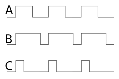
Figure 1: Different duty cycles: 50% (A), 75% (B), and 25% (C) duty cycles
The duty cycle is a measure of how long a device operates compared to its rest period. For example, if a device operates for 10s on and then 10s off and repeats, the duty cycle would be 50%. The duty cycle rating is crucial for understanding how long an actuator can run without risking overheating, especially in electric actuators. This article discusses the essential aspects of duty cycle in linear actuators and valves, like duty cycle formula, the variation of duty cycle in different types of valves and actuators, and how to determine duty cycle using a multimeter.
Table of contents
- Duty cycle equation
- Duty cycle and pulse width
- Duty cycle vs frequency
- Duty cycle in different types of valves
- How to check duty cycle with multimeter
- Factors affecting duty cycle
- FAQs
View our online selection of valves!
Duty cycle equation
Duty cycle indicates the proportion of time the signal is ON compared to the entire cycle duration. It is typically expressed as a percentage and is calculated using the formula:
For example, if a valve actuator operates for 30 seconds and rests for 90 seconds, the duty cycle is 30/(90+30)×100 = 25%. This means the actuator is active 25% of the time and inactive 75% of the time. Similarly a 70% duty cycle is a signal that is ON 70% of the time and OFF the other 30%.
This ratio is crucial for selecting the appropriate actuator for a specific application, ensuring that the motor does not exceed its thermal limits during operation. Every actuator has a limit to how much heat it can handle before it starts to get damaged or its performance is affected. For instance, an actuator with a 25% duty cycle should not be run at a rate that meets or exceeds 25%.
For processes requiring frequent valve adjustments, a higher duty cycle enhances efficiency by allowing more frequent flow modulation. However, it's crucial to balance this with the actuator's thermal limits to avoid damage.
Duty cycle and pulse width
Pulse width refers to the duration for which a signal remains in the ON state, typically measured in milliseconds. Duty cycle, on the other hand, is the ratio of the pulse width to the total cycle time, expressed as a percentage.
When the valve is activated for different lengths of time using pulse-width modulation, the duty cycle changes. For instance, if the valve is turned on for 0.03 seconds during a 0.1-second cycle, the duty cycle is 30%. If it is turned on for 0.08 seconds within the same 0.1-second cycle, the duty cycle becomes 80%.
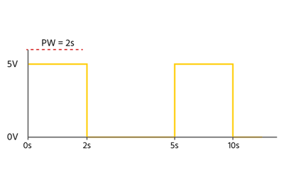
Figure 3: A waveform showing pulse width equal to 2s. The duty cycle in this case is 2/5 ×100 = 40%.
Duty cycle vs frequency
The frequency of operation is how often the complete cycle repeats in one second. Consider a solenoid valve used in an irrigation system. The valve has a duty cycle of 50%. Let's say the total cycle time is 20 seconds. This means:
- The valve is open for 10 seconds (50% of 20 seconds).
- The valve is closed for 10 seconds (the remaining 50%).
Since the cycle time is 20 seconds, the frequency is:
Frequency = 1 cycle / 20 seconds = 0.05 Hz, or one cycle every 20 seconds
In this example, the duty cycle helps ensure the valve does not overheat or wear out by operating continuously, while the frequency determines how often the watering occurs. The duty cycle and frequency should be within the values specified by the manufacturer.
Duty cycle in different types of valves
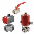
Ball valves
Ball valves, especially those with electric actuators, are commonly used in applications requiring tight sealing and quick response times. They are suitable for high-duty cycle applications due to their robust design and ability to handle high pressures and large volumes. However, care must be taken to ensure the actuator's duty cycle is not exceeded to prevent overheating.
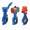
Butterfly valves
Butterfly valves are often used in large-diameter pipelines where space is limited. They are less suited for high-duty cycle applications compared to ball valves due to their design, which may not provide as tight a seal. However, they are efficient for applications with moderate duty cycles and where quick actuation is not critical.
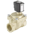
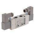
Solenoid valves
Regular duty solenoid valves are designed for intermittent use, requiring cooling periods between activations to prevent overheating. They can handle high power during short ON periods but must remain OFF for a specific time, with duty cycles typically ranging from 25% to 50%. For example, a solenoid with a 25% duty cycle can operate for 15 seconds and needs 45 seconds of rest. These are suitable for applications like starter motors and intermittent valve control. In contrast, continuous duty solenoid valves have a 100% duty cycle, allowing them to operate indefinitely without cooling periods. They are built for lower power levels and enhanced thermal management, making them ideal for applications requiring constant operation, such as RV battery charging systems.
How to check duty cycle with multimeter
It's crucial to measure the duty cycle of a system, particularly when dealing with systems that involve pulse-width modulation (PWM) or other forms of signal modulation. In systems using PWM for controlling power delivery, such as motor speed controllers, LED dimmers, or heating elements, measuring the duty cycle helps ensure that the system is operating at the desired power level. When analyzing digital signals, measuring the duty cycle can help verify that signals are being transmitted correctly, with the expected ON and OFF times. Perform the following steps to measure the duty cycle:
- Prepare the multimeter: Set the multimeter to measure frequency by rotating the dial to select frequency (Hz) (Figure 3 labeled A). Press the button Hz/% to select frequency/duty cycle measurement mode (Figure 3 labeled B). This step can vary across multimeter models, so refer to the product catalog for the exact configuration.
- Insert test leads: Insert the black test lead into the COM (common) jack and the red test lead into the V Ω jack.
- Connect to the circuit: Connect the test leads to the circuit to be tested and take the readings.
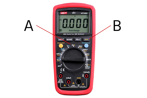
Figure 3: Set the multimeter dial to frequency (A) and press the Hz/% button (B)
Factors affecting duty cycle
The duty cycle varies between different actuators and is often specified in product descriptions.
For some actuators, particularly DC actuators, the duty cycle can also depend on the load they are handling. A heavier load can increase the current draw and heat generation, potentially reducing the duty cycle. To address this, manufacturers often provide charts in their catalogs that show how the duty cycle changes with different loads. These charts help users determine the appropriate duty cycle for their specific application, ensuring that the actuator operates within safe thermal limits and maintains reliability and efficiency.
- Fluid load: The amount of fluid load on a valve affects its duty cycle. Higher loads require more power to actuate, reducing the duty cycle. Conversely, lower loads allow for longer operation times.
- Environmental conditions: Temperature and humidity can impact the duty cycle. High temperatures can reduce the actuator's ability to dissipate heat, while high humidity can affect electrical components, potentially leading to reduced performance.
-
Actuator type: Different actuators (electric, pneumatic, hydraulic) have varying duty cycle capabilities.
- The duty cycle in pneumatic actuators are generally less constrained by thermal considerations because they do not rely on electric motors that generate significant heat. Instead, they use compressed air to drive the actuator, which typically allows for more frequent cycling and continuous operation without mandatory rest periods. This makes them particularly suitable for applications requiring frequent cycling and rapid response, making them ideal for demanding environments.
- Electric actuators are limited by their thermal management capabilities. Electric actuators are limited by specific duty cycle constraints, often defined by standards such as the IEC – S4 classification. These constraints typically restrict the actuator to operating only for a defined amount of the time within a given period to prevent overheating. The fixed speed of electric actuators can complicate tuning, as it may lead to overshoot and stability issues. For applications requiring continuous operation, specialized continuous duty electric actuators are available, but they come at a higher cost.
FAQs
Why is solenoid valve duty cycle important?
Duty cycle ensures the solenoid valve operates efficiently without overheating, balancing on-time and off-time for optimal performance.
What is a continuous duty cycle solenoid?
A continuous duty cycle solenoid is designed to operate continuously without overheating, suitable for applications requiring constant activation.


