Selecting Between Grounding Rods And Plates In Different Soil Conditions

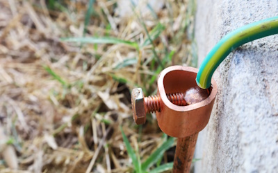
Figure 1: Ground rod
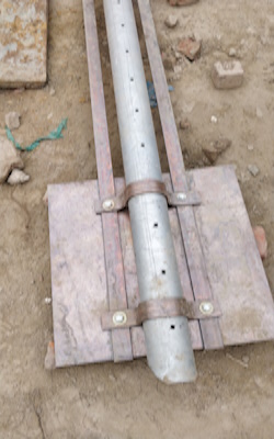
Ground rods (Figure 1) and ground plates (Figure 2) are essential in building and other structures' electrical grounding or earthing systems. Their primary purpose is to provide a low-resistance path for electrical current to flow into the earth in the event of a fault or lightning strike. Choosing between ground rods and plates is critical in designing an electrical system's safe and effective grounding path. This decision depends heavily on the surrounding soil type. This article delves into the impact of soil conditions on the selection of grounding electrodes and explores the crucial aspects to consider for optimal system design.
Table of contents
View our online selection of grounding rods and braid connectors!
Ground plate vs ground rod for different soil

Figure 2: Ground plate
The choice between ground rods and plates depends on various factors, including soil conditions, available space, and local electrical codes. Here's a general guide to help select between them based on different soil conditions:
Rocky or very hard soil
- Ground rods: Driving ground rods in rocky or hard soils can be difficult without special equipment. They can still be effective if one can drill a deep enough hole to accommodate the rod.
- Ground plates: Ground plates are easier to install in rocky conditions because they can be buried in a trench and require less depth.
Clay soil
- Ground rods: Clay soil typically has good conductive properties due to its moisture content. Ground rods are usually suitable for clay soils, as they can be driven down to the required depth to achieve a low-resistance connection to the earth.
- Ground plates: While not as commonly needed in clay soils, ground plates can be used if the soil is too dense for rods or has a high water table.
Sandy or gravelly soil
- Ground rods: Sandy or gravelly soil tends to have poor conductivity due to low moisture retention. Therefore, longer ground rods might be necessary to reach a depth with adequate soil moisture.
- Ground plates: Ground plates can be less effective in sandy or gravelly soils due to their large surface area and poor conductivity, but they can be used if installed at a depth where the soil is more moist.
Loamy soil
- Ground rods: Loamy soil is ideal for ground rods because it typically has a balance of sand, silt, and clay, providing good conductivity and ease of driving rods.
- Ground plates: There is usually no need for ground plates in loamy soil unless it's a preference or specified by local codes.
Wet or marshy soil
- Ground rods: Wet or marshy soils are highly conductive, so ground rods can be very effective. However, the soil may be too soft to support the rods and could corrode faster.
- Ground plates: Ground plates can be used if installed below the water table to ensure good conductivity.
Other factors
When deciding between ground rods and plates, it's also important to consider other factors, such as:
- Conductive soils: Ground rods are preferred due to their cost-effectiveness and deep penetration.
- Non-conductive soils: Ground plates are recommended for their larger surface area and ability to overcome high soil resistance (discussed later).
- Shallow installations or limited space: Ground plates offer more flexibility and are easier to install in shallow areas where driving rods are challenging.
In all cases, it's essential to measure the ground resistance after installation to ensure that it meets the requirements set by the National Electrical Code (NEC) or other governing bodies. Multiple grounding electrodes can be interconnected to achieve the required resistance level.
Table 1: Ground rod vs ground plate
| Feature | Ground rod | Ground plate |
| Suitable soil conditions | Deep, homogenous soils | Shallow, layered soils, high-resistivity soils |
| Installation process | Easy | More difficult |
| Installation depth | Minimum depth of 2.4 meters (8 feet) | Minimum depth of 0.6 meters (2 feet) |
| Surface area | Small | Large |
| Resistance | High | Low |
| Corrosion susceptibility | High | Low |
Soil testing
Testing the soil before installing a ground rod or plate is crucial. By understanding soil characteristics, one can determine the most suitable type of grounding electrode and the installation depth required to achieve a low-resistance path to earth. Here are some procedures and considerations for soil testing:
- Visual inspection: Begin with a simple visual examination of the soil where the grounding system will be installed. Look for indications of soil type, moisture content, and rocks or other obstructions.
-
Soil resistivity testing:
- Soil resistivity is a key factor in selecting and designing a grounding system. It measures the resistance of the soil to conduct the electric current and is typically expressed in ohm-meters (Ω-m).
- The Wenner Four-Pin method is a common technique for measuring soil resistivity. It involves driving four equally spaced metal rods into the ground and passing a current between the outer two rods while measuring the potential difference between the inner two rods. The distance between the rods and the measured voltage calculates the soil's resistivity.
- 𝞺: Resistivity
- a: Distance between rods
- V: Measured potential difference
- I: Current
- Soil sampling and analysis: Soil samples can be collected and sent to a laboratory for detailed analysis. The lab can provide information about soil composition (sand, silt, clay, organic matter), pH levels, and corrosive properties. Knowing the soil pH and chemical composition is important because highly acidic or alkaline soils and soils with high salt content can accelerate the corrosion of metallic grounding components.
- Moisture content measurement: Soil moisture greatly affects resistivity, with wetter soils generally having lower resistivity. Measuring soil moisture can help predict how grounding system performance might change with seasonal variations in soil moisture.
- Temperature effects: Soil temperature can also influence resistivity. While it's harder to measure and account for, it is worth noting that colder temperatures can increase soil resistivity.
- Corrosivity testing: If the soil is suspected to be corrosive, specific tests can determine the presence and concentration of elements that may corrode metal grounding components. This will influence the choice of materials and protective measures.
High soil resistivity
Soil resistivity can significantly increase the overall resistance of the grounding system. Here are some options to consider when encountering high soil resistivity:
- Use longer or additional ground rods to reduce resistance.
- Consider using chemical ground rods that release ions to improve conductivity.
- Install a ground plate at a depth where the soil is more conductive.
- Use conductive backfill around the ground rod or plate to lower resistance.
- Treat the soil with chemicals or moisture to reduce resistivity.
Read our grounding overview article for more details on how electrical grounding works.
FAQs
How to drive a ground rod in rocky soil?
Use a rotary hammer drill or dig a hole to sidestep rocks, then backfill and drive the rod.
Can ground rods be driven at an angle?
Yes, at up to 45 degrees if vertical driving is impossible due to obstructions.
Can ground rods be installed horizontally?
If depth is unattainable, rods can be buried horizontally in a trench at least 76 cm (30 inches) deep.
Why do ground rods need to be deeper in desert soil than other soil types?
Desert soil has high electrical resistivity, making it more difficult for electricity to flow through the soil, so ground rods must be driven deeper to reach a point where the soil is more conductive.
Why is soil testing important for ground rods?
Soil testing helps choose the right ground rod length and placement to ensure safe & effective grounding in different soil conditions.


