How To Determine Moment Load

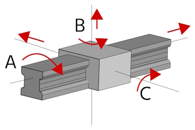
Figure 1: Rotational force along three axes: roll (A), yaw (B), and pitch (C)
Moment load is the force that causes an object to rotate or bend and is a critical factor in the design and application of linear actuators like pneumatic cylinders. Linear actuators are engineered to withstand specific levels of moment loading, defined as the permissible range. Exceeding these limits introduces additional forces on the actuator's guide system, which can degrade performance and significantly reduce service life.
Calculating moment load is essential to ensure that an actuator can handle twisting or bending forces, preventing system failure and maintaining efficient operation. This helps in selecting the right components and designing systems that are safe, reliable, and long-lasting. Understanding moment load is important for:
- Component selection: Choose components that can handle expected moment loads under both static and dynamic conditions.
- System design: Design systems to minimize moment loads by reducing the distance between the load and pivot point or using counterweights.
- Maintenance and monitoring: Regularly inspect for wear or misalignment due to excessive loads and implement monitoring systems to detect load changes.
Table of contents
View our online selection of pneumatic cylinders!
What is moment load?

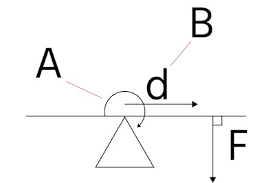
Figure 2: Rotational force on objects: direction of rotation (A), torque arm (B), force (F), and the perpendicular distance from the axis of rotation to the line of action of the force (d)
Moment load is the result of a force (F) applied at a distance (d) from an axis, creating a tendency for rotation around that axis. This rotational force, or torque, can be applied in three primary directions:
- Roll (Figure 1 labeled A): Rotational movement around the axis
- Yaw (Figure 1 labeled B): Lateral movement to the left or right
- Pitch (Figure 1 labeled C): Upward or downward movement
It's crucial to calculate moment loads before selecting a pneumatic cylinder, installing it in an application, or making changes to the load or mounting configuration.
Moment load calculation
Moment load formula is given by:
M = F × d
Where:
- M: Moment load
- F: The applied force
- d: The moment arm distance from the axis
To determine the overall moment load, consider the moments in each direction (pitch, yaw, roll) and compare them to the permissible moments specified for the actuator. The sum of the ratios of these moments to their permissible values should be less than 1.0 for an acceptable configuration.
Example
Consider a robotic arm used in an industrial setting for tasks such as assembly, welding, or material handling. This robotic arm is equipped with actuators that control its movement and positioning. Each actuator must handle various forces and moments as the arm moves and interacts with objects.
For instance, consider the robotic arm is tasked with picking up a heavy object. The force exerted by the weight of the object, combined with the distance from the actuator's axis of rotation (the moment arm), generates a moment in the pitch direction. Similarly, if the arm needs to rotate or pivot while holding the object, moments in the yaw and roll directions may also be generated.
To ensure the arm operates safely and efficiently, it's necessary to calculate the moments in the pitch, yaw, and roll directions and compare these to the actuator's permissible limits, as seen in Table 1.
Table 1: Example calculations of pitch, roll, and yaw moments for a linear actuator
| Direction | Force (N) | Moment arm distance (m) | Calculated moment (Nm) | Permissible moment (Nm) | Ratio |
| Pitch | 30 | 0.5 | 15 | 30 | 0.5 |
| Yaw | 15 | 0.3 | 4.5 | 15 | 0.3 |
| Roll | 5 | 0.2 | 1 | 10 | 0.1 |
The sum of the ratios (0.9) is less than 1.0, indicating that the configuration is acceptable and within permissible limits. If the final ratio exceeds acceptable limits, consider reducing the applied forces, shortening the moment arm distances, or upgrading to actuators with higher permissible moments. Alternatively, adjust the arm configuration or redistribute the load to balance the moments more effectively.
Factors affecting moment load
When calculating moment loads in industrial applications, several factors can influence the results:
- Actuator size and mass capacity: The size of the actuator, for example, the diameter and stroke length of a pneumatic cylinder, plays a crucial role in determining its ability to handle forces and moments. Larger cylinders, with greater diameter and stroke, can accommodate higher pressures and generate more force, allowing them to manage larger moments. Additionally, the mass being transported affects the magnitude of these forces, with heavier loads generating larger moments. The structural integrity and design of the cylinder must be sufficient to support these loads without deformation or failure.
-
Positioning:
- Vertical: Gravity significantly impacts vertical cylinders, increasing downward speed and requiring more force for upward motion, which can affect energy consumption and system wear.
- Horizontal: Gravity mainly affects friction and alignment, potentially increasing moment loads if the load is unevenly distributed.
- Load positioning: The center of gravity's location is crucial. If it overhangs the support, it creates additional moments, leading to imbalances and increased stress on the system.
- Actuator capabilities: The actuator must handle the forces and moments effectively. Advanced control systems can help manage dynamic effects and imbalances, improving precision and reducing wear.
Static and dynamic moment loads
Moment loads can be dynamic, occurring during operation due to factors like gravity and acceleration, or static, present when the system is at rest. Both types of moment loads can affect the alignment and performance of components.
Table 1: Static and dynamic moment loads
| Aspect | Static moment load | Dynamic moment load |
| Definition | Load that remains constant or changes very slowly over time | Load that varies with time due to motion or external forces |
| Time dependency | Time-independent | Time-dependent |
| Predictability | Predictable and easier to design for | Complex and often unpredictable |
| Examples | Weight of a stationary object on a beam | Forces on a rotating arm due to changing speeds |
| Analysis | Focuses on equilibrium and material strength | Considers inertia, damping, and time-dependent factors |
| Design considerations | Emphasizes strength and stability | Requires flexibility, damping, and energy absorption |
FAQs
How is the moment calculated?
Moment is calculated by multiplying the force applied by the perpendicular distance from the pivot point to the line of action of the force.
What is a load moment indicator on cranes?
A load moment indicator (LMI) on cranes calculates the load moment (product of load weight and radius) to ensure it stays within safe limits, preventing overloading and enhancing safety.


