


Pipe Flanges Overview
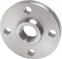
Figure 1: Threaded pipe flange
Pipe flanges are one of the most used connection types for pipes. These connections consist of three different parts: the pipe flange, a gasket, and bolting. They are used for various industrial applications, pressure classes, and media. They can connect piping in a system, connect components such as valves, containers, vessels, and many more applications. These connectors benefit from a straight-through connection without loss of flow or pressure. This article explores the most common pipe flange variants, their uses, and their most commonly used applications.
Table of contents
- How do pipe flanges work?
- Standard types of pipe flanges
- Other flange types
- Pipe flange face variants
- Common pipe flange materials
- Pipe flange classification and pressure rating
View our online selection of pipe flanges!
How do pipe flanges work?
Flanges are used to bolt piping components together, such as pipes, valves, fittings, pressure components, and more. Joining is done using bolts that join two parts together, with a gasket in between to ensure the connection is leak-free. Piping is connected to the flange by use of a threaded connection, a weld such as the connection in Figure 2, or through the use of a stub-end.
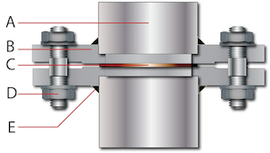
Figure 2: The components of a pipe flange connection: pipe (A), flange (B), gasket (C), bolting (D), and weld (E).
Standard types of pipe flanges
Threaded Flange
Threaded flanges are joined using the male thread on a pipe and the female thread inside the bore of the flange. Typically, these do not need to be welded together, although doing so will strengthen the connection. If the connection is not welded, a thread tape or liquid sealant is recommended. This flange type is generally used for relatively low pressure and low temperatures, such as water and compressed air.
In gasoline stations and other areas where the risk of explosions is high, threaded flanges are mandatory. Welding in these environments would pose a significant danger.
Figure 3: Threaded flange
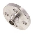
Welding neck flange
A welding neck flange has a long-tapered hub that can be welded to a pipe. This type of pipe flange is used for high-pressure applications with high or low temperatures and offers an unrestricted flow of the media in the piping. Because there is no obstruction, there are no issues with turbulence, erosion, or corrosion of the joints. The pipe and flange should be connected through a full penetration V-shaped butt weld. The purpose of this type of weld is to transmit the full load-carrying capacity of the components.
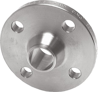
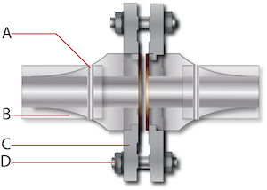
Figure 4: An example of a welding neck flange connection. Pipe to flange v-shaped butt weld (A), pipe (B), flange (C), and bolting (D).
Long welding neck
Like the weld neck flanges, although these flanges have an extended neck that is not tapered. The neck, in this case, acts as a bore extension. Industrial weld neck flanges are used in high-pressure applications and high temperatures. These flanges usually have the same bore sizes as pipes in the same system, although this can be adjusted as needed.
Applications include those in the oil, gas, and petrochemical industries. They are often used as nozzles and to replace pipe sections. They can withstand higher pressures and find their use in water mains and factory piping systems. Long neck welding flanges usually have a square end instead of the beveled edge available on welding neck flanges.
A butt weld joint connects the weld neck flanges. For high-pressure applications such as drilling rig standpipes, welding the neck will make a strong connection and is a good option for pressure vessels.
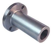
Figure 5: Welding neck flanges
Slip-on flanges
These flanges are similar to threaded flanges in appearance but lack the thread inside the flange. Instead, the pipe is held in place by two fillet welds, one on the outside of the flange and one on the inside. Also known as tee joints, these welds consist of two pieces of metal perpendicular to one another. The ID of the flange is slightly larger than the OD of the pipe. This allows the pipe to slide into the flange snuggly before being welded into place.
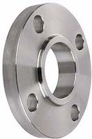
Figure 6: Slip-on flange
Socket weld flange
These flanges are used primarily for small-size and high-pressure pipes. The pipe is slotted into the flange and held there using a solid fillet weld outside the socket flange. There should be an expansion gap between the shoulder and the end of the pipe. These flanges are not suitable for highly corrosive environments as the expansion gap between the pipe end and the socket's shoulder is susceptible to crevice corrosion.
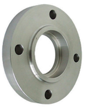
Figure 7: Socket weld flange pipe
Lap joint flange
The use of lap joint flanges effectively minimizes the cost of connections in stainless steel or nickel alloy pipeline systems. These flanges are always used in combination with stub ends so that the flange itself can be of a lower grade, cheaper, material, such as carbon steel, while the stub end, which comes into contact with the media in the system, can be of the same material as the piping system. The pipe can be welded in place with a butt weld for extra strength.
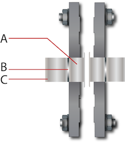
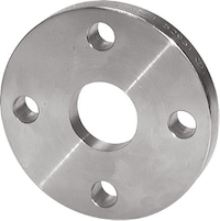
Figure 8: Components of a lap joint flange connection (left) and a lap joint flange (right). The pipe is welded with a butt weld on the back of the stub end (B), the lap joint flange (A) slides over the pipe (C), and is held in place by the pressure from the bolts.
Blind flange
Blind flanges seal or close a pipeline to block fluid flowing. It is easy to access the pipeline when the blind flanges are unbolted so that the operator can perform activities inside the terminal end of the pipeline. These are mounted against flat face-type joints.

Figure 9: Blind flange
Other flange types
Besides the more standard flange types mentioned above, more varieties have been designed for specialistic applications. Below we cover these specific types:
Nipoflange
Nipoflanges are used for pipeline branches at 90 degrees. Nipoflanges are formed by combining a welding neck flange with a forged Nipolet in a single piece of forged steel. Installing a Nipoflange involves welding the Nipolet part on the run pipe and bolting the flanged portion to the branch pipe.
Weldoflange
A Weldoflange is similar in design to a Nipoflange; they are a combination of a weld neck flange and a branch fitting connection called a Weldolet. Weldoflanges are made out of a single piece of solid forged steel.
Swivel flange
The swivel ring flange allows quick alignment of bolt holes on mating flanges. This feature is ideal for installing large pipelines, offshore and subsea pipelines that transport oil, gas, hydrocarbons, and other demanding fluids in petrochemical applications. Swivel flanges combine a welding neck on one pipe and the swivel on the other pipe. They are then connected by the rotation of the swivel flange on the pipe so that the bolts can be connected easily.
Expander flange
Expander flanges are used to increase the bore of the pipeline from one specific point to another or connect pipes to other mechanical devices such as pumps, compressors, and valves with different inlet sizes. Expanding flanges can only increase the run pipe bore by a maximum of two sizes. A standard flange and a buttweld reducer should be used for larger pipe bore increases.
Reducer flange
The function of a reducer flange is opposite that of an expander flange. A reducer flange allows the pipeline bore to be decreased. It is only safe to reduce the bore of the run pipe by one or two sizes; otherwise, a buttweld reducer and a standard flange must be used.
Storz flange
Storz couplings are often used and designated as fire hose couplings. However, they have wide usage in many industries, including refineries, agricultural, construction, maritime safety, and military use due to their resistance against corrosion, acids, and water. The storz flange has a storz coupling on one side, and a flat face on the other. To learn more about Storz, read our technical article.
Pipe flange face variants
The choice of face type will significantly impact flanges' performance and service life. A flange's facing determines both the type of gasket required for installation and the characteristics of the seal it creates. Below is an overview of the most common face variants.

Figure 10: Face variants: Flat face (FF), raised face (RF), lap joint (LJ), ring joint (RTJ), male and female (M&F)
- Flat Face (FF): A flat face flange has an even, flat surface combined with a full-face gasket covering a large portion of the flange surface.
- Raised Face (RF): These flanges are equipped with a small raised ring around the bore and a gasket inside the bore circle.
- Lap Joint (LJ): The lap joint connection means that the stub end facing is also the flange facing; this makes it similar to the raised face.
- Ring Joint Face (RTJ): The grooves and raised areas in these flanges match. This design provides a reservoir for gasket adhesive and allows the flanges to self-align during installation.
- Male & Female (M&F): The gasket is secured with matching grooves and raised sections, similar to tongue and groove flanges. In contrast to tongue and groove flanges, these retain the gasket on the female face, providing more accurate positioning and a more comprehensive range of options for gasket materials.
- Seal finish: Many types of faces have either a serrated or smooth finish. It is important to choose between the options because this will determine the optimal gasket for a reliable seal. Metallic gaskets are best used with smooth faces, while soft gaskets benefit from serrated faces.
Common pipe flange materials
Carbon steel, high yield carbon steel, alloy steel, stainless steel, duplex, and super duplex steel, are the most common materials used for pipe flanges. However, nickel alloy grades such as Inconel, Incoloy, Hastelloy, and Monel are also used for some applications. For more information on the chemical properties of these materials, refer to our chemical resistance page.
Carbon steel
Flanges made from Carbon steel have excellent chemical and mechanical properties. In addition to having excellent fatigue strength, high strength, superior chemical resistance, and high toughness, carbon steel is also highly resistant to stress corrosion cracking. This makes it an ideal material for connecting pipes.
Alloy steel
Compared to carbon steel, alloy steel contains a more significant amount of chromium and molybdenum. For applications requiring high pressures and temperatures, alloy steel is ideal. As compared to carbon steel, alloy steel is more corrosion resistant.
Duplex steel
Duplex steels combine austenite and ferrite phases. Duplex steel is corrosion-resistant and more rigid than ferritic steel. The material is highly corrosion resistant in chloride and sulfur environments. Due to its magnetic properties, duplex steel can be used in many complex industrial applications.
Stainless steel
Nickel (Ni), chrome (Cr), and molybdenum (Mo) distinguish stainless steel material from other materials. Stainless steel is popular because of its superior corrosion resistance. It can be used to fabricate pipe flanges of all sizes and types. Learn about stainless steel in our 304 vs. 316 stainless steel comparison.
Pipe flange classification and pressure rating
The pressure rating for a pipe flange, sometimes called class, #, or Lbs, is the maximum allowable pressure a pipe flange can withstand at increasing temperatures. There are seven different flange pressure ratings: 150, 300, 400, 600, 900, 1500, and 2500 according to ANSI/ASME B16.5.
This becomes especially important when choosing the correct flange for your application. For example: if we take two flanges with the same bore, 10 inches, the same material, carbon steel, but different pressure ratings, 300#, and 1500#, then:
- The lower-rated flange will be less robust, smaller, and lighter
- The higher-rated flange will be stronger, bigger, and heavier
- The 300# will be rated for a pressure of 50.1 bar at 50° C
- The 1500# will be rated for a pressure of 250.6 bar at 50° C
