Solenoid Valve Connectors

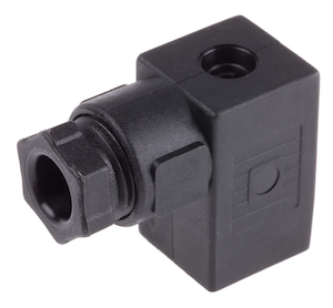
Figure 1: Figure 1: A DIN C solenoid valve connector
A solenoid valve connector connects the solenoid valve to a power source. Different types of connectors are available to match the wide range of solenoid valves. The standard on the connector and the solenoid valve must match to ensure a proper connection. This article discusses the main features of solenoid valve connectors and how to select one for an application.
View our selection of solenoid valve connectors!
Solenoid valve connector types
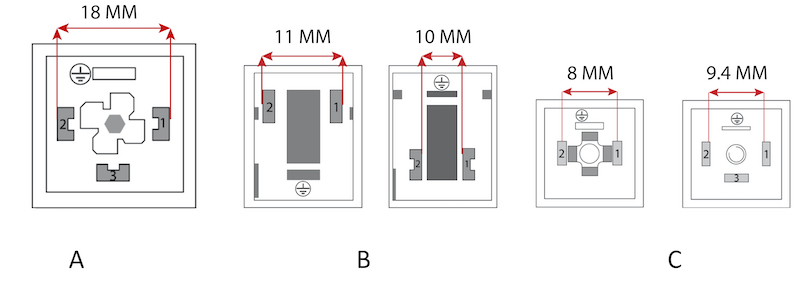
There are three basic solenoid valve connectors: Form A, Form B, and Form C. These connectors are governed by the DIN standards:
- DIN EN 175301-803 Form A
- DIN EN 175301-803 Form B
- DIN EN 175301-803 Form C
These standards were formerly known as DIN 43650 Form A, Form B, or Form C.
Table 1: Basic properties of solenoid valve connectors
| Parameter | Form A | Form B | Form C |
| Size | Largest | Middle | Smallest |
| Pin spacing | 18 mm | 10 mm or 11 mm | 8 mm or 9.4 mm |
| Number of pins | 2 plus ground or 3 plus ground | 2 plus ground | 2 plus ground or 3 plus ground |
| Pin shape | U-shape |
|
Flat blade |
| Base shape | Square | Rectangle | Square |
| Note | - | Also called micro connector | Also called sub-micro connector |

Figure 2: Diagrams of solenoid valve connectors, forms A, B, and C.
How to select solenoid valve connectors
- Voltage: Choose a connector that matches the solenoid valve's voltage requirements. The connectors are available in both AC and DC variants.
Table 1: Different voltage ranges for solenoid valve connectors
| Voltage type | Voltage range | Applications |
| Low voltage | 12-24V | Automotive, battery-powered, and basic industrial equipment |
| Medium voltage | 100-240V | Typical wall outlets and commercial systems |
| High voltage | Up to 400V | Heavy-duty industrial equipment |
- Seal material: A solenoid valve connector seal prevents dust, moisture, and contaminants from entering. Select based on the environmental conditions and chemical exposure that the connector will face.
- NBR is suitable for applications requiring resistance to oils and fuels.
- Thermoplastic polyurethane offers excellent abrasion resistance and flexibility. Read our chemical compatibility chart for more information.
-
Connector features:Consider the available features to ensure the connector is suitable for an application:
- LED indicator: Provides a visual indication of whether the coil is energized.
- Varistor: Protects the power supply and solenoid valve from voltage spikes.
- Rectifier: Converts AC power to DC power, with options for 90% or 45% conversion depending on the type.
- Pole protection and freewheeling diode: Safeguards a DC power supply from transient voltage spikes.
- Recovery diode: Protects against voltage spikes by allowing current to bypass the solenoid coil when de-energized, preventing damage.
- Over-excitation: Delivers a higher current for faster solenoid valve response.
-
Electrical connection: Choose the DIN connectors for solenoid valves based on their standard requirements. The connectors are available in 2-pin and 3-pin configurations without additional circuits.
- Form A: Best for large, robust applications
- Form B: Ideal for medium-sized applications
- Form C: Perfect for compact setups
- Cable length: Determine the required cable length based on the distance between the solenoid valve and the power source.
-
Degree of protection: Look for environmental protection standards like IP65 or IP67.
- IP65 provides protection against dust and water jets, suitable for most industrial environments.
- IP67 offers additional protection against temporary immersion in water, ideal for more demanding conditions.
- Nominal current: Match the nominal current rating to the solenoid valve's requirements. A higher current rating ensures the connector can handle the electrical load without overheating, especially in high-power applications.
Read our solenoid valve installation article for more details on solenoid valve connector wiring.

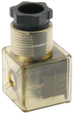
Figure 3: A Form A solenoid valve connector with LED.
FAQs
What is a solenoid valve DIN connector?
A DIN connector is a standardized connector that connects solenoid valves to electrical circuits, ensuring secure and reliable connections.
Why use a solenoid valve connector with LEDs?
It helps quickly diagnose the valve's status, making maintenance and troubleshooting more efficient.


