Solenoid Valves & Power Supply Voltage

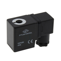
Figure 1: 24V DC solenoid valve coil
Understanding solenoid valve voltage is essential to ensure the coils work correctly and last longer. Solenoid valve coils come in different voltage ratings. These ratings must match the power supply to work correctly and last long. Using a coil with the wrong voltage can cause poor performance or damage. This article covers why voltage matching is essential and discusses the best practices when choosing or troubleshooting solenoid valve coils.
Table of contents
- Considerations for solenoid coil design parameters
- Are solenoid valve coils interchangeable?
- Practical examples
- Troubleshooting and best practices
- FAQs
View our online selection of solenoid valves!
Considerations for solenoid coil design parameters
A solenoid valve uses an electromagnetic coil to move a valve mechanism. The coil is a wire (usually copper or aluminum) wound around a hollow core. Solenoid coils work with either direct current (DC) or alternating current (AC). Common voltage ratings are 6V, 12V, 24V, 120V, and 220V.
- Coils with less than 24 volts are used in small devices like home appliances, cars, and basic automation tools.
- Coils above 24 volts are used in factories and heavy machines.
Solenoid valve operating voltages
The nominal voltage is the voltage needed for the valve to operate. This value is usually written on the valve body or coil.
Under voltage
Using less than the nominal voltage can slow the valve's response or prevent it from working. Most coils can handle voltage within ±10% of the rated value. For example, a 220V AC coil usually operates between 198V and 242V. Symptoms of low voltage are:
- The plunger does not move - the coil may overheat and burn out.
- Slow valve action
- Excessive noise
- Heating of the coil
Use a multimeter to check the power supply voltage. If the voltage is correct, replace the coil.
Over voltage
Applying more than the rated voltage makes the valve respond faster. But this doesn't always mean the system operates quicker. Too much overvoltage can seriously damage the coil. Problems caused by overvoltage are:
- Coil failure due to overheating
- More heat, which breaks down coil parts
- Shorter valve lifespan
Manufacturers warn against exceeding the rated voltage. A brief spike of up to 50–100% more voltage can be tolerated, but only for about one second. Extended exposure causes quick coil failure.
Frequency considerations for AC coils
AC solenoid coils are built to operate at specific frequencies, usually 50Hz or 60Hz. Frequency affects how current flows and the coil's magnetic strength. Using a 50Hz coil on a 60Hz supply, or the other way around, may reduce efficiency and cause overheating or damage.
For example, a 230V 50Hz coil should not be used on a 230V 60Hz supply unless the manufacturer agrees. A higher frequency lowers the coil’s resistance, increasing current and heat. Some coils are rated for both 50Hz and 60Hz to avoid this problem.
Cost
DC systems often cost more to build than AC systems. This is because the operating current for a DC supply is higher than that for an AC supply, necessitating additional measures to prevent voltage drops on the return line.
Inrush current and holding current
AC solenoids experience a high inrush current followed by a smaller holding current. If the plunger gets stuck during inrush, the coil heats up quickly, which may cause burnout. This issue often relates to AC coils and is due to valve problems like a jammed plunger, which is not always a defective coil.
Are solenoid valve coils interchangeable?
AC vs DC solenoid coils
AC solenoid coils run on alternating current. They switch polarity many times per second and use shading rings to reduce noise and vibration. They are common in industrial settings where high power and fast response are needed.
DC solenoid coils run on direct current, which gives a steady magnetic field. They are simpler and don’t need shading rings. DC coils are used where precise control and low power use are essential, such as in cars and small tools.
Interchangeability considerations
-
Voltage compatibility:
- The new coil must have the same voltage as the old one. A 24V DC coil should replace another 24V DC coil.
- AC coils resist current more than DC coils. An AC coil on a DC supply without changes can overheat and damage the coil.
-
Physical fit:
- The replacement coil must match the original coil in size and how it mounts.
-
Electrical properties:
- Impedance and resistance: AC coils have different impedance characteristics than DC coils. Using an AC coil in a DC circuit, or vice versa, without proper adjustments can lead to improper operation or damage.
- Shading rings: AC coils often include shading rings to reduce vibrations. DC coils do not have this feature. Using a DC coil instead of an AC coil might cause operational issues.
For example, putting a 24V DC coil in place of a 24V AC coil can cause a malfunction due to missing shading rings. Also, a DC coil used where AC is expected may draw too much current and burn out.
In short, solenoid coils of AC and DC types are not always interchangeable. Voltage ratings, size, and electrical features must all match.
Practical examples
Using a 110V power supply for a 120V solenoid valve
Ensuring the correct solenoid valve voltage is vital when connecting a 110V power supply to a 120V solenoid valve. A 120V coil with a ±10% voltage range can work between 108V and 132V. Since 110V falls within the solenoid valve voltage range, it is compatible. However, working at the low end may reduce the coil’s magnetic force, slowing the valve's action.
Note: Always check the coil’s voltage tolerance from the manufacturer to avoid problems.
Using a 24V DC power supply for a 12V DC solenoid coil
This setup creates a serious overvoltage.
- Applying 24V to a 12V coil will send too much current, causing overheating and likely failure.
- The coil is made for 12V, so the resistance is low. Double the voltage means four times more power (P = V²/R).
To use a 24V supply safely with a 12V coil:
- Use a voltage step-down device like a a href="/pages/power-converter">DC-DC converter</a>.
- Use current-limiting circuits to avoid overcurrent during startup.
Troubleshooting and best practices
- Overheating: Excessive heat can indicate a voltage mismatch or insufficient current handling.
- Erratic operation: Inconsistent operation or failure to actuate can result from improper voltage or frequency.
- Noise and vibration: Unusual sounds or vibrations may signal electrical or mechanical incompatibility.
Tips for selecting the right coil and power supply
- Match voltage and current type: Ensure the coil's voltage rating and current type (AC or DC) match the power supply.
- Check voltage tolerance: Verify that the power supply voltage falls within the coil's specified tolerance range.
- Consider frequency for AC coils: Ensure the power supply frequency matches the coil's design (e.g., 50Hz or 60Hz).
FAQs
Are solenoid valve coils AC or DC?
They can be either AC or DC, based on how and where they are used.
How to test a 12V solenoid coil?
Apply 12V and use a multimeter to check resistance. Look for continuity and compare resistance to the manufacturer’s specifications.


