Electric Ball Valve With Timer
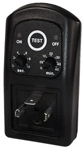
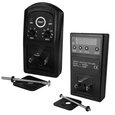
Figure 1: Analog timer used with electric ball valves
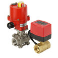
An electric ball valve with a timer can be used to adjust and automate the time interval during which the valve remains open and closed. Both analog and digital timers can be connected to electrically actuated ball valves. These valves are popularly used in automatic condensate drains and lubricating systems. This article discusses the details of analog and digital timers used in electric ball valves and their installation process.
Table of contents
- Timer controlled motorized ball valve
- Analog timer
- Digital timer
- Safety instructions while installing timer
- Ball valve with timer applications
View our online selection of ball valves and timers!
Timer controlled motorized ball valve
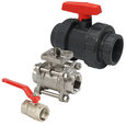
A ball valve is a shut-off valve that controls the flow of a liquid or gas using a rotary ball having a bore. A ball valve can be operated manually through a lever or actuated electrically or pneumatically. Connecting a timer helps automate the valve's opening and closing interval for electrically actuated ball valves. The time periods during which the valve remains on and off can be programmed within the timer yielding an effortless operation. For example, the timer can be programmed to open a ball valve for 20 minutes and keep it off afterward simply by setting the interval time (20 minutes in this case) on the timer panel. The main advantage of this operation is that no human intervention is required to turn the valve on or off after a certain interval; hence, these systems can be installed in remote locations where human intervention may be difficult but the application requires an on/off function.
Analog timer
An example and one of the most common analog timers for electric ball valves is the robust SMD-720. The switch has a repeating on-off program with an adjustable pulse (on) of 0 to 10 seconds and an interval time (off) of 0 to 45 minutes. The program can be stopped by interrupting the power supply. The timer is compatible with the EN 175301-803 connector (formerly DIN 43650A).
Product description
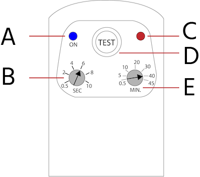
Figure 2: Analog timer's front panel: LED status in the ON position (A), LED status in the OFF position (B), OFF time (C), ON time (D), and TEST button (E).
- A: The LED lights up in the ON position
- B: Set the ON time in seconds. For example, rotating and setting the knob to 4 will send a pulse signal for 4 seconds into the ball valve. The valve remains on during this interval.
- C: LED lights up in the OFF position.
- D: Press the TEST button to restart the loaded program. The last used program is stored in the memory and is active (in the initial state) when the power supply is reconnected, or the TEST button is pressed.
- E: Set the OFF time in minutes. For example, rotating and setting the knob to 30 minutes will disconnect any electric signal sent to the ball valve, stopping its operation.
Analog timer installation
Electrical connection
Read our article on electric ball valve installation for the details process of connecting ball valve terminals to the power supply. Install the timer between the ball valve and the connector. Ensure that all parts are clean and free from moisture. Position the rubber seals correctly to protect the construction against moisture. Tighten the screw (with torque less than 0.5 Nm) until the rubber seals properly.
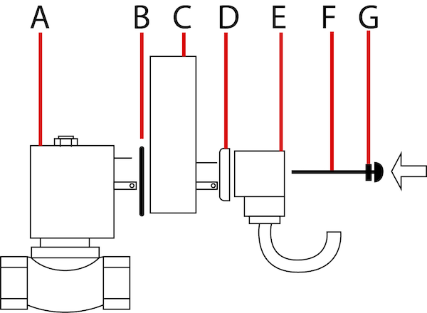
Figure 3: Analog timer installation components: ball valve (A), rubber seal (B), timer (C), rubber seal (D), connector (E), screw (F), and rubber gastet (G).
Setup program
The timer has a repeating ON-OFF program as seen in Figure 4. The ‘ON’ period determines the time duration during which the valve opens and the ‘OFF’ period determines the break time during which the valve goes idle. To restart the program, press the TEST button or switch the power supply off and connect again. Rotate the knobs by hand or with the help of a screwdriver to set the desired ‘ON’ and ‘OFF’ periods. The left knob (ON period) is indicated in seconds, while the right knob (OFF period) is indicated in minutes.

Figure 4: Waveform showing the ball valve’s ON and OFF periods
Digital timer
As the name suggests, a digital timer displays the ball valve’s ON and OFF periods using numbers. An example of a common digital timer, is the robust AF-TD timer that can be programmed to set an ON and OFF perios anywhere between 0 and 100 hours. The timer is compatible with a DIN-A connector, and it can be programmed to operate in three different operating modes which are discussed in the next section.
The product specification of a digital timer for ball valves is shown in Figure 5.
- A: An LED that lights up in the ON position
- B: Set the time duration using this button
- C: Mode button to set the mode of operation. Digital timers work in various modes, as discussed in the next section.
- D: An illuminated display that shows the chosen time
- E: ‘ENTER’ button to confirm the chosen settings
- F: Restart the last mode saved
A digital timer is installed on a ball valve in the same way as an analog timer discussed in the previous section.
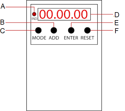
Figure 5: A digital timer's front panel: ON position LED (A), button to set the time duration (B), mode button (C), time display (D), ENTER button to confirm the settings (E), and button to restart the last mode saved (F).
Programming the digital timer
The digital timer can be set with three different programs:
- ON-OFF cycle (repeating)
- OFF-ON cycle (repeating)
- ON period (single ON period and OFF afterward)
ON-OFF cycle (repeating infinitely)
- Press the ‘MODE’ button on the panel until the display shows ‘ON-OFF.’
- Set the ‘ON’ period by pressing the ENTER button. The first two digits indicate the hours, the middle two digits indicate the minutes, and the last two digits indicate the seconds. Adjust the flashing digit by pressing the ADD button. Press the ENTER button to go to the next digit. Once the last digit is set, and the ENTER key is pressed, the first digit will flash. In the same way, set the OFF time period.
- For example, for an ON-OFF cycle with ON time equal to twenty minutes and OFF time equal to thirty minutes.
- Choose the mode as ‘ON-OFF.’
- Press the ENTER button.
- Use the ADD button to choose the digit as 0. Then press ENTER to move to the next digit. Again select 0. Then press ENTER to move to the third digit and select 2 using the ADD button. Continue this process until the last digit completes. Ensure that the display shows 00:20:00.
- Repeat the last two steps to set the OFF period similarly. Ensure that the display shows 00:30:00.
- Once the last digit of the OFF period is set and confirmed by pressing the ENTER key, the text ‘ON-OFF’ flashes for 3 seconds before the cycle starts. This is the interval when the timer passes the current to the valve actuator to start operation. The indicator on the left side of the panel lights up during this period.
- Pressing the RESET button immediately turns on the timer while the text ‘ON-OFF’ appears on display for three seconds. After this period, the ON-OFF cycle starts again. A temporary power interruption has the same effect as the RESET button.
- Pressing the MODE button interrupts the timer putting it in the OFF position. The screen displays the current mode ‘ON-OFF.’ Press the MODE button multiple times to select a different mode.
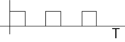
Figure 6: Waveform showing ON-OFF cycle
OFF-ON cycle (repeating infinitely)
- Press the ‘MODE’ button on the panel until the display shows ‘OFF-ON.’
- Set the ‘OFF’ period by pressing the ENTER button. The first two digits indicate the hours, the middle two digits indicate the minutes, and the last two digits indicate the seconds. Adjust the flashing digit by pressing the ADD button. Press the ENTER button to go to the next digit. Once the last digit is set, and the ENTER key is pressed, the first digit will flash. In the same way, set the ON time period. For example, for an OFF-ON cycle with OFF time equal to ten minutes and ON time equal to 50 minutes.
- Choose the mode as ‘OFF-ON’
- Press the ENTER button
- Use the ADD button to choose the digit as 0. Then press ENTER to move to the next digit. Again select 0. Then press ENTER to move to the third digit and select 1 using the ADD button. Continue this process until the last digit completes. Ensure that the display shows 00:10:00
- Repeat the last two steps to set the ON period similarly, and ensure that the display shows 00:50:00.
- Once the last digit of the ON period is set and confirmed by pressing the ENTER key, the text ‘OFF-ON’ flashes for 3 seconds before the cycle starts. The indicator on the left side of the panel lights up during this period.
- Pressing the RESET button immediately turns on the timer while the text ‘OFF-ON’ appears on display for three seconds. After this period, the OFF-ON cycle starts again. A temporary power interruption has the same effect as the RESET button.
- Pressing the MODE button interrupts the timer putting it in the OFF position. The screen displays the current mode ‘OFF-ON.’ Press the MODE button multiple times to select a different mode.
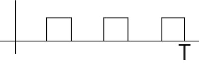
Figure 7: Waveform showing OFF-ON period
ON-OFF cycle (single period ON, afterward OFF)
- Press the ‘MODE’ button on the panel until the display shows ‘ON.’
- Set the ‘ON’ period by pressing the ENTER button. The first two digits indicate the hours, the middle two digits indicate the minutes, and the last two digits indicate the seconds. Adjust the flashing digit by pressing the ADD button. Press the ENTER button to go to the next digit. Once the last digit is set, and the ENTER key is pressed, the first digit will flash. For example, set an ON period of 2 hours 20 minutes (02:20:00) as follows:
- Choose the mode as ‘-ON-’
- Press the ENTER button
- Use the ADD button to choose the digit as 0. Then press ENTER to move to the next digit. Then select 2. Then press ENTER to move to the third digit and select 2 using the ADD button. Continue this process until the last digit completes. Ensure that the display shows 02:20:00.
- Once the last digit is set and confirmed by pressing the ENTER key, the text ‘-ON-’ flashes for 3 seconds before the cycle starts. This is the interval when the timer passes the current to the valve actuator to start operation. The indicator on the left side of the panel lights up during this period. Once the ON period has elapsed, the timer will close the power supply to the solenoid valve, and the display will show "-. -. -".
- Pressing the RESET button immediately turns on the timer while the text ‘-ON-’ appears on display for three seconds. After this interval, the ON period starts. A temporary power interruption has the same effect as the RESET button.
- Pressing the MODE button interrupts the timer putting it in the OFF position. The screen displays the current mode ‘-ON-.’ Press the MODE button multiple times to select a different mode.
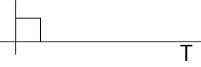
Figure 8: Waveform showing ON-OFF cycle(single period ON, afterward OFF)
Safety instructions while installing timer
- Install the product in a dry and ventilated environment. In the case of a moist environment, ensure that no moisture can penetrate the coil or device. Take sufficient care to install the device safely to avoid burning, electric shock, or other injuries. Keep the device away from flammable materials.
- Perform the installation only when the system is cooled down, depressurized, and electrically disconnected.
- To prevent the risk of electric shock and the device getting activated accidentally, always ensure to turn off the power supply before installation.
- Ensure commissioning after the installation process gets complete.
Ball valve with timer applications
- Shower timer
- Lubricating systems
- Automatic condensate drain
- Air dryers
- Compressed air timer workshop


