Switches For Electric Ball Valves

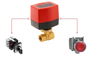
Figure 1: Connecting a switch to an electric ball valve allows users to conveniently control the valve's operation.
When wiring switches to electric ball valves, ensuring proper connections and a secure setup is crucial for safe and efficient operation. This guide provides detailed instructions for connecting various switches to an electric ball valve, including a normally open push-button switch, a rotary control switch, and a standard light switch. Achieve reliable control over an electric ball valve by following these directions, whether it needs a simple on/off mechanism or a more complex latching relay setup.
Important notes
There are important steps to take no matter what type of switch connects to a ball valve:
- Identify the power source: Ensure the power source is suitable for each component in the circuit. If not, consider using multiple power sources of different voltages or using devices to protect equipment (e.g., transformers and relays).
- Prepare the wires: Strip the wire ends to fit into the terminals of the circuit components.
- Specific instructions: Follow any specific wiring instructions or color codes provided by the electric ball valve manufacturer and include any additional components (e.g., resistors, diodes, or relays) if specified in the wiring instructions.
- Secure all connections: Double-check all connections to ensure they are tight and secure. Use electrical tape or wire connectors to insulate any exposed wires.
View our online selection of electric ball valves!
Connect a normally open push-button switch to an electric ball valve
This section outlines how to connect a normally open push-button switch to an electric ball valve so that pushing the button turns on the valve, and pushing it again turns the valve off. This is done using the internal limit switches within the actuator to maintain the power to the electric ball valve until the next push. A typical installation will follow these steps:
- Connect power supply to switch: Connect the positive wire from the power supply to the common terminal (COM) of the push-button switch.
- Connect the switch to the actuator: Connect a wire from the NO terminal of the switch to the control wire of the electric ball valve actuator.
- Connect ball valve to power source: Connect the negative terminal of the ball valve directly to the negative wire of the power supply.
- Power the actuator: Ensure the actuator is properly powered by connecting its power terminals to the power supply.
How it works
Upon the first button press, the normally open (NO) contact of the switch momentarily closes, sending a pulse to the actuator. This action causes the actuator to start moving the ball valve to the open position. The internal limit switch within the actuator will automatically stop the motor once the valve reaches the fully open position, even after the button is released. When the button is pressed a second time, another pulse is sent to the actuator, causing it to move the ball valve to the closed position. The internal limit switch will again stop the motor once the valve reaches the fully closed position. After releasing the button, the actuator remains in its current state, ensuring the ball valve stays in the desired position.
Wiring a rotary control switch to an electric ball valve
A rotary control switch is a versatile device used to control the flow of electricity in a circuit by rotating a knob to different positions. This section explains how to wire a two-position rotary control switch to an electric ball valve, including identifying terminals, connecting the power supply, and ensuring safety.
-
Identify the terminals on the control switch:
- Typically, a control switch will have terminals for input (power) and output (to the device being controlled).
-
Connect the power supply to the control switch:
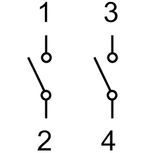
- Connect the positive terminal of the power supply to terminal 1 on the control switch.
- Connect the negative terminal of the power supply to terminal 3 on the control switch.
-
Connect the control switch to the electric ball valve:
- From terminal 2 on the control switch, run a wire to the positive terminal of the electric ball valve.
- From terminal 4 on the control switch, run a wire to the negative terminal of the electric ball valve.

Figure 2: Rotary control switch wiring diagram. Terminals 1 & 3 are input terminals and 2 & 4 are output terminals.
How it works
When the switch is in the "Off" position, there is no power flow because the circuit is open, meaning there is no electrical connection between the power supply and the electric ball valve. In this state, the electric ball valve remains in its default position, which could be either open or closed depending on its design. Conversely, when the switch is in the "On" position, the circuit is closed, allowing electrical current to flow from the power supply to the electric ball valve. This initiates the activation of the ball valve, causing it to change its state. If the valve was previously closed, it will open, and if it was open, it will close, depending on the valve's configuration.
Connect a light switch to an electric ball valve
This section provides a step-by-step guide on how to connect a standard light switch to an electric ball valve. Ball valves with light switches are not common valve control systems in industrial applications. They are more often found in DIY systems, such as campers or off-the-grid setups. This setup allows a user to control the valve's state by toggling the switch. Follow these instructions for a typical installation:
- Identify the power source: Ensure the power source is suitable for the voltage and current requirements of both the light switch and the electric ball valve actuator.
- Prepare the wires: Strip the ends of the wires to fit securely into the screw clamp terminals of the light switch and the electric ball valve actuator.
-
Connect power supply to light switch
- Connect the positive wire from the power supply to the input terminal (often labeled "Line" or "L") of the light switch.
- Connect the negative wire from the power supply to the common terminal (often labeled "Neutral" or "N") of the light switch.
- Be sure to read any manufacturer's instructions that may come with the light switch in case it doesn't have obvious input and common terminals.
-
Connect the light switch to the electric ball valve
- Run a wire from the output terminal (often labeled "Load" or "L1") of the light switch to the positive terminal of the electric ball valve actuator.
- Connect the negative terminal of the electric ball valve directly to the negative wire of the power supply.
- Secure all connections: Double-check all connections to ensure they are tight and secure. Use electrical tape or wire connectors to insulate any exposed wires.
How it works
When the switch is in the "Off" position, the circuit is open, meaning there is no electrical connection between the power supply and the electric ball valve. In this state, the electric ball valve remains in its default position, which could be either open or closed depending on its design. Conversely, when the switch is in the "On" position, the circuit is closed, allowing electrical current to flow from the power supply to the electric ball valve. This initiates the activation of the ball valve, causing it to change its state. If the valve was previously closed, it will open, and if it was open, it will close, depending on the valve's configuration.


