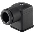
Burkert 2518 Cable Plug - How They Work
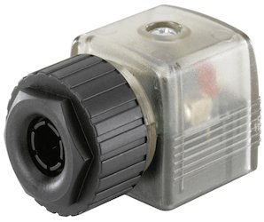
Figure 1: Burkert 2518 Connector with LED
The Burkert 2518 cable plug connects a power source to an electrical component, such as a valve. It offers modular and compact designs suitable for various applications. Each version complies with DIN EN 175301-803 Form A (DIN-A), ensuring quick assembly and reduced integration time. The Burkert 2518 is available in multiple designs to meet different protection, indication, or performance needs. Standard connectors are rated IP65 or IP67 and connect at a 90-degree angle to the component.
Note:The Burkert 2508 cable plug has been discontinued and is directly replaced by the Burkert 2518 cable plug. There is no HL, LR, or IN circuit functions in the Burkert 2518 as there was in the Burkert 2508..
Buy Burkert 2518 Online Now!
Table of contents
- DIN EN 175301-803 Form A
- Connectors without Circuit Functions: 2-Pin & 3-Pin
- Connectors with Circuit Functions
- Connector Options
- Wiring overview
DIN EN 175301-803 Form A
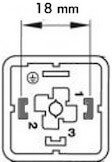
Figure 2: DIN EN 175301-803 Form A standard sizing
All Burkert Type 2518 configurations adhere to DIN EN 175301-803 Form A standard (previously DIN 43650). These connectors are also called “MPM” or “sugar cube connectors”. They are designed to meet various overvoltage protection requirements and to function within certain voltage limits. Form A refers to the distance between the pins, which can be seen in Figure 2. The standard also defines smaller connectors which are named Form B and C. The majority of solenoid valves are compatible to this standard. Before ordering a connector, check if the valve connection has the same form size.
Connectors without circuit functions: 2-Pin & 3-Pin
Connectors without circuitry can be ordered with a 2-pin or 3-pin design. Both adhere to DIN-A standard and are suitable for applications that don’t require specific electrical protection or increased performance. 2-pin and 3-pin connectors without circuitry can be supplied with AC or DC voltage and include an extra pin for an earth conductor.
Connectors with circuit functions
LED
An LED (light-emitting diode) circuit is used for valve power status indication. The benefits of an LED include reduced installation time and faster electrical troubleshooting. This circuit is suitable for applications that use an AC or DC power supply. See our wiring diagram that shows the available voltage, max amperage, and available length cables.
To ensure proper circuit operation, three characteristics of an LED must be considered. First, an LED will only emit light with the correct electrical polarity. This is because the LED is a diode and only allows current to flow in one direction. Second, the voltage drop across the positive to negative terminal of the LED must be greater than the “forward voltage” rating of the LED. The forward voltage is the minimum voltage required to conduct current. Finally, the brightness of an LED is dependent on the amount of current flowing through it. Although the relationship between current and brightness is nonlinear, the max current should not be exceeded. Selecting an LED circuit based on the power supply and valve voltage class will ensure these three operational requirements are met.
Varistor
A varistor circuit is used to protect the power supply and valve from voltage spikes. This circuit function is suitable for AC or DC applications. See our wiring diagram that shows the available voltage, max amperage, and available length cables.
The resistance of a varistor varies nonlinearly as voltage is applied across it. Under nominal voltage conditions the resistance is high. As the voltage across a varistor increases the resistance will decrease. When the varistor is exposed to a large voltage spike its resistance becomes very small which causes the varistor to conduct and clamp the voltage to a safe level. Unlike diodes, varistors are bidirectional and will function regardless of polarity.
Rectifier
A rectifier circuit is used to rectify an AC power supply to DC power, therefore, it is well suited for applications with an AC power supply used on a DC rated coil. The rectifier in this circuit is a full-wave rectifier, so it converts 90% of the AC voltage into DC. For example, if you input 230VAC it will output 207VDC. DC solenoids are quieter, no in-rush current, and can be battery operated when compared to an AC solenoid. However, AC solenoids can run on line power, have quicker response times, and run cooler. See our wiring diagram that shows the available voltage, max amperage, and available length cables.
A full wave rectifier circuit will reduce the varying magnetic field by redirecting current flow to one direction. A full wave bridge rectifier is composed of diodes in a bridge configuration. Diodes will only conduct current in one direction. When diodes are arranged in a bridge configuration the negative current flowing into the rectifier will be redirected to positive flowing current at the output. Although the polarity at the output will always be positive, the waveform will not be completely smooth resulting in a lower effective output voltage to the solenoid coil. Therefore, the dc output voltage should be taken into consideration when selecting a supply voltage and can be calculated with the following formula:
VDC = VAC * 0.9
Pole protection and freewheeling fiode
A pole protection and freewheeling diode circuit are used together to protect a switching DC power supply from transient voltage spikes. When a solenoid coil is energized with a power supply a magnetic field is generated. After the power supply is switched off, the decay of the magnetic field causes a short-term back electromotive force (EMF) voltage which can cause arcing across the switch. To prevent this, a freewheeling diode, also known as a fly back diode, is placed across the load. When the switch is open, current will be redirected through the diode instead of the switch. This allows the current to be dissipated through the coil instead of across the switch. The polarity of the freewheeling diode in relation to the supply is critical in its ability to redirect current back through the coil and protect the switch. Pole protection is used to ensure the polarity of the supply is always correct by using a diode to control current flow. If the incorrect polarity is detected, current will not be conducted through the coil. Due to the conductance properties of diodes, this circuit is only functional with DC power and DC rated coils.See our wiring diagram that shows the available voltage, max amperage, and available length cables.
Connector options
The Burkert 2518 is available in various connector options with combinations of features to satisfy the requirements of your application. The following options are available:
- Without circuit (2-pin)
- Without circuit, 3-pins + protective earth conductor
- LED
- Rectifier, LED, and Varistor
- LED and Varistor
- Varistor
- Pole protection, Free Wheeling Diode, and LED
- Pole protection and Free Wheeling Diode
- Rectifier and Varistor
Wiring overview
Before wiring, special consideration should be taken in regards to the voltage and current range of the connector. Earth ground wiring should also be considered as the main purpose of it is for protection against electrical shock. An earth conductor provides a path to ground during an electrical fault. Proper grounding techniques should always be used to protect people and equipment from electrical shock. It is also used to protect electrical components from electromagnetic interference (EMI), which can reduce performance and life span of electrical components.
The table below shows symbols for each circuit component:
| Circuit Component | Symbol |
| Wire |  |
| Earth Ground |  |
| Coil |  |
| LED |  |
| Diode | 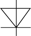 |
| Varistor |  |
| Resistor |  |
The table below shows the corresponding wiring diagram and acceptable input voltage and max current ranges for each connector option. They are all available with no cable, 1 m cable, 3m cable, or 5 m cable.
| Circuitry | Wiring Schematic | Voltage | Max Current |
| Without circuit, 2-pin | 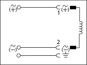 |
0 - 250V AC/DC | 16A 10A (VDE, UL) 8A (CSA) |
| Without circuit, 3-pins + protective earth conductor | 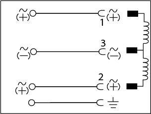 |
0 - 250V AC/DC | 16A 10A (VDE) |
| LED |  |
12 - 24V AC/DC | 10A |
| 100 - 120V AC/DC | 10A | ||
| 200 - 240V AC/DC | 10A | ||
| Rectifier, LED, and Varistor | 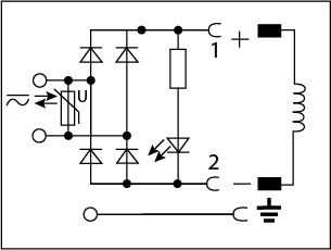 |
12 - 24V AC/DC | 1A |
| 100 - 120V AC/DC | 1A | ||
| 200 - 240V AC/DC | 1A | ||
| LED and Varistor | 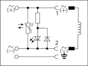 |
12 - 24V AC/DC | 10A |
| 100 - 120V AC/DC | 10A | ||
| 200 - 240V AC/DC | 10A | ||
| Pole protection, Free Wheeling Diode, and LED | 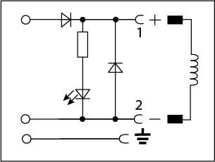 |
12 - 24V DC | 1A |
| Pole protection and Free Wheeling Diode | 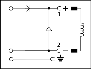 |
12 - 240V DC | 1A |
| Rectifier and Varistor | 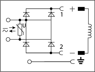 |
200 - 240V AC/DC | 1A |
| Varistor | 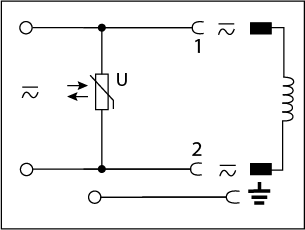 |
12 - 24V AC/DC | 10A |
| 100 - 240V AC/DC | 10A |


