Limit Switch Boxes For Pneumatic Quarter-Turn Valves
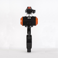
Figure 1: A limit switch box mounted on a pneumatic actuator mounted on a butterfly valve.
Limit switch boxes enhance safety by monitoring actuator positions to prevent accidents, improving efficiency by enabling precise control, and extending equipment longevity. They are engineered to withstand diverse operating environments thanks to their durable construction and compatibility with various temperatures and explosive atmospheres. This introduction outlines limit switch boxes' primary advantages and suitability for PAL quarter-turn pneumatic actuators. It highlights their design features, such as visual position indicators, adjustable set points, and various switch options, collectively contributing to their reliability, safety, and ease of integration into existing control systems.
The benefits of a limit switch box
Limit switch boxes are important tools for monitoring pneumatic actuators, devices used in various industries to move or control valves. Here are the main benefits of using limit switch boxes:
- Safety: They make operations safer by monitoring the position of the actuator. If the actuator moves too far or not far enough, the limit switch box can detect this and help prevent accidents or damage to equipment.
- Efficiency: These boxes help actuators work more precisely, reducing mistakes and the need for redoing tasks. This means processes can run smoother and faster, saving time and money.
- Longevity: With proper maintenance, limit switch boxes can last a long time, often 10 to 15 years. This makes them a reliable part of the system, contributing to the overall durability of the equipment they are used with.
Limit switch box design
Here are the main features of a limit switch box:
-
Visual position indicator
- Allows for easy and quick visual inspection of the valve's position.
- Typically includes a clear or open window showing a colored indicator that moves with the valve stem.
-
Mechanical or proximity switches
- Mechanical switches are activated by physical movement, while proximity switches detect the presence of an object without physical contact.
- Used to send a signal when the valve reaches its open or closed position.
-
Adjustable set points
- Enables precise setting of switch activation points.
- Allows for customization according to specific operational requirements.
-
Enclosure protection
- Designed to protect internal components from dust, water, and other environmental conditions.
- Enclosures are often rated by NEMA or IP standards to ensure suitability for various environments.
-
Direct mounting to actuators
- Can be directly mounted to pneumatic actuators via standardized interfaces (e.g., NAMUR VDI/VDE 3845).
- Simplifies installation and ensures proper alignment.
-
Electrical connections
- Includes options for various types of electrical connections, such as terminal blocks or pre-wired connectors.
- May offer compatibility with different voltages and types of control signals (e.g., AC, DC, digital).
-
Material construction
- Constructed from materials suitable for the operating environment, such as aluminum, stainless steel, or engineered plastics.
- Ensures durability and resistance to corrosion.
-
Compatibility with control systems
- Designed to integrate seamlessly with PLCs (Programmable Logic Controllers) and other control systems.
- Can support various communication protocols for integration into automated systems.
-
Safety and compliance
- Meets relevant safety and regulatory standards, ensuring reliability and safety in operation.
- May include certifications such as ATEX for use in explosive atmospheres.
-
Manual override
- Some models include a feature for manual operation, allowing the valve to be operated manually in case of an emergency or system failure.
Operating principle
Limit switch boxes mount directly to the shaft of a pneumatic actuator, either using a coupling or by direct mount. The actuator's shaft connects to a cam or similar mechanism that interacts with limit switches in the box. These limit switches (mechanical, inductive, capacitive, or magnetic) position at points that correspond to the valve's open and closed positions.
When the pneumatic actuator receives a signal to open or close the valve, it rotates the valve stem by 90°.The attached cam inside the limit switch box simultaneously rotates. The cam then engages the limit switches at designated positions, which are typically the 0° and 90° positions. When the limit switches are engaged, the position of the switch changes from open to closed for vice versa.
Some limit switch boxes have visual indicators that make it simple for an operator to see whether a valve is open or closed. Other limit switches send a feedback signal to a control system, which can use system data to make decisions such as stopping the actuator, initiating other processes, and more.
Selection guide for limit switch boxes
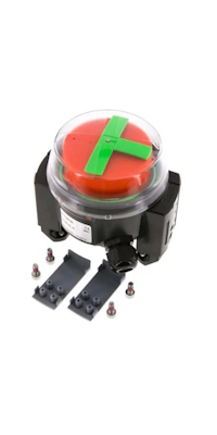
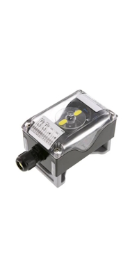
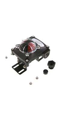
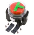
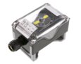
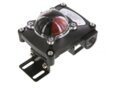
Figure 3: Common limit switch box series: compact (left), standard (center), and heavy-grade (right).
When choosing between compact, standard, and heavy-grade limit switch boxes, it is important to consider their similarities and differences to ensure the correct product selection for the application. Below is a guide to help make an informed decision.
Similarities
- Protection class: All models offer high protection with IP 67 ratings, except for one variant of the Standard limit switch box (V3HH9) with an IP 65 rating.
- Connection dimensions: Each model fits hole patterns of 80 x 30 mm and 130 x 30 mm, ensuring compatibility with various actuators.
- Position indicator: All models feature a position indicator, making it easy to monitor the status of the switch.
Differences
-
Materials
- Compact: Entirely made out of plastic, focusing on compactness and weight reduction.
- Standard: Primarily uses PA6 for housing and assembly bridge, with screws made of stainless steel (1.4301), indicating a lighter construction.
- Heavy-grade: Housing and screws are made of die-cast aluminum and stainless steel/zinc-plated steel, respectively, offering robustness under UV light. These devices can also be submerged up to 0.5 meters for no longer than one hour.
-
Temperature range
- Compact: -20 °C to 70 °C, the most limited range, suitable for moderate environments.
- Standard: -20 °C to 80 °C, with a variant (V3HH9) that operates between -10 °C and 60 °C, indicating a slightly narrower range.
- Heavy-grade: -25 °C to 85 °C, suitable for more extreme conditions.
-
Shaft height adjustment
- Compact: Offers the widest range of adjustment from 20 to 50 mm, accommodating a broader range of applications.
- Standard: Variable between 20 and 30 mm, offering flexibility but not compatible with size 50 PAL actuators.
- Heavy-grade: Adjustable between 15 and 25 mm.
-
Switch options
- Compact: Micro switches, inductive sensors, and NAMUR inductive sensors (ATEX)
- Standard: Micro switches, inductive sensors, and NAMUR inductive sensors (ATEX), 3/2 pneumatic valve
- Heavy-grade: Micro switches
-
Special considerations
- Standard: May require a spacer plate (V2N28) for assembly on actuators of size 1 in connection with NAMUR valve, indicating potential additional considerations during installation.
Conclusion
- Select the Compact limit switch box for applications where space is at a premium, and the flexibility of switch options and a wider shaft height adjustment range are beneficial.
- Opt for the Standard limit switch box for versatility in a wide range of actuators, keeping in mind the potential need for additional components in specific setups.
- Choose the Heavy-grade limit switch box for robust applications requiring durable materials and operation in more extreme temperatures.
How to mount a limit switch box onto a pneumatic actuator
These instructions provide a general guide on how to mount a limit switch box onto a pneumatic actuator. It is crucial that the person responsible for mounting the limit switch box reads the device's specific mounting instructions carefully before proceeding.
- Safety first: Always follow the safety instructions provided with the limit switch box and actuator.
- Position the actuator: Move the actuator to its end position, ensuring the groove of the drive shaft is parallel to the actuator housing.
- Place the limit switch box: Position the limit switch box on the actuator using the appropriate mounting bridge.
- Secure the mounting bridge: Use the four supplied locking screws to fasten the mounting bridge onto the actuator.
- Open the housing: Loosen the four cover screws to open the limit switch box housing. Be careful not to unscrew the screws completely; they should remain attached to the cover.
- Cable installation: Feed the system cable through the cable gland into the housing. Then, wire the individual wires to the terminal block according to the terminal diagram found on the data sheet or inside the housing cover. Ensure the housing is connected to the potential equalization.
- Close the housing: Place the cover back on the housing, making sure the seal is correctly positioned. Tighten the cover screws securely to ensure the housing is properly sealed.
PAL quarter-turn pneumatic actuators
It's important to ensure the limit switch box is compatible with the actuator. PAL quarter-turn pneumatic actuators are ready to pair with a limit switch box. PAL actuators are often used for the following specifications:
- PAL actuators are a cost effective option for actuating larger ball and butterfly valves with an ISO 5211 top flange, ranging from F03 to F12.
- They produce a torque between 9.92 Nm and 901.8 Nm at 8 bar pressure.
- They can be single acting (spring open or close) or double acting for better control.
- They operate in temperatures between -20 °C to 80 °C, with an option for higher temperature seals for up to 120 °C or 150 °C.
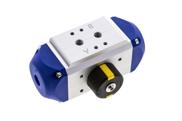
Figure 2: A PAL series pneumatic actuator for quarter-turn valves.
FAQs
What is a limit switch box?
A limit switch box is a device that monitors and indicates the position of pneumatic quarter-turn valves, ensuring precise control and safety.
How does a limit switch box work with a pneumatic actuator?
It mounts on the actuator, using switches to signal the valve's open or closed position, enhancing control and safety in automation systems.
Why use a limit switch box for valves?
Limit switch boxes provide accurate valve position feedback, crucial for process control, safety, and efficiency in industrial applications.
What features do limit switch boxes for pneumatic quarter-turn valves have?
They feature visual indicators, adjustable set points, and various switch options, designed for reliability and easy integration into control systems.