Pneumatic Cylinder Force Calculator
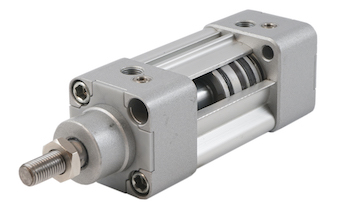
Figure 1: Pneumatic cylinder
Pneumatic cylinders convert compressed air energy into mechanical motion. Several types of pneumatic cylinders are designed to meet specific performance requirements, such as force, speed, and precision. A critical factor to select the right pneumatic cylinder for a particular application is its force output. The correct force output ensures that the cylinder can perform the desired task effectively and safely.
This article explores the force generated by single-acting and double-acting pneumatic cylinders. To understand how they work, please read our pneumatic cylinder article.
View our online selection of pneumatic cylinders
Necessary force to move an object of a given mass
When choosing a pneumatic cylinder to move a load, a frequently asked question is how to determine the needed force.
Derivation
- F: The necessary force to move an object
- m: Mass of the body
- a: The acceleration required to move the body
Acceleration is the rate of change of velocity ('v') of the body.
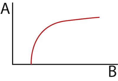
Figure 2: Ideal velocity profile of a pneumatic cylinder showing the constant maximum velocity (A) and linear acceleration at maximum force (B). The X-axis and Y-axis show the piston position and velocity, respectively.
The pneumatic cylinder velocity increases linearly until the maximum velocity is reached (Figure 2); the acceleration is constant in this linear region.
- v2: Maximum velocity
- v1: Initial velocity
Taking the initial velocity as zero,
- L: Pneumatic cylinder stroke length
- t: Full stroke time
Once the user knows the mass of the object to be moved, the stroke length and the full stroke time, the above relation can be used to calculate the force necessary to move the object. Once this value is calculated, select a pneumatic cylinder that produces this force. For example, for a full stroke time of 1 s, F = mL, and for a full stroke time of 5 s, F = mL/25. Therefore, as the full stroke time reduces, the necessary force output to move the object should increase and vice versa.
Note: The derivation for pneumatic cylinder force explained above doesn't take into account the effects of friction on the movement of the object.
Example
Calculate the force required to move an object of mass 1000kg using a pneumatic cylinder with a stroke length of 20mm and full-stroke time of 1s.
m = 1000kg
L = 20mm = 0.02m
t = 1s
F = ma
a = dv/dt = (L/t)/t = 0.02 m/s2
F = 1000 × 0.02 = 20N
Choose a pneumatic cylinder that can produce 20N.
How to calculate pneumatic cylinder force
This section explains the force generated by a pneumatic cylinder. The force calculations for single- and double-acting cylinders can be theoretical or effective. The theoretical calculations are simpler but do not take into account system friction or the spring force. However, the theoretical calculation allows for a quick determination of the cylinder's max force. The effective force calculation does take friction and the spring force into account. Therefore, the output is lower than the theoretical result.
Theoretical pneumatic cylinder force
The basic formula to calculate the theoretical force of a pneumatic cylinder is:
- Ft: theoretical force in Newtons (N)
- P: the pressure exerted by the fluid on the piston in Pascals (Pa)
- Au: effective area in contact with the gas in square meters.
Single-acting pneumatic cylinder theoretical force
The effective area in a single-acting pneumatic cylinder is:
where 'D' is the piston diameter, also referred to as the bore diameter.
Hence the force equation for a single-acting pneumatic cylinder is,
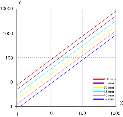
Figure 3: Pneumatic cylinder pressure versus force for various cylinder diameters. The X-axis and Y-axis plot the air pressure (kPA) and Force (N), respectively.
For a given pressure, the force generated by a pneumatic cylinder will increase as the diameter of the cylinder increases. This is because the effective area of the piston increases as the diameter increases, which in turn, increases the force generated by the cylinder.
Also, for a given cylinder diameter, the force generated by a pneumatic cylinder will increase as the pressure applied to the cylinder increases. This is because the pressure acts over a larger area, which in turn generates a greater force.
Example
Consider a single-acting pneumatic cylinder with a piston diameter of 40 mm, and a system pressure of the system is pressurized to 400 kPa. Calculate the maximum force exerted by the cylinder.
D = 40 mm
P = 400 kPa
Therefore, the cylinder exerts a force of 502 N when a single-acting pneumatic cylinder with a piston diameter of 40 mm is pressurized to 400 kPa.
Double-acting pneumatic cylinder theoretical force
In a double-acting cylinder, the useful area (Au) is given by,
for the forward stroke
for the return stroke
- D: Piston diameter
- d: Rod diameter
A piston is a component of a pneumatic cylinder that moves back and forth within the cylinder to transmit force. It is typically a cylindrical-shaped object that is located inside the cylinder.
The piston rod, on the other hand, is the component that connects the piston to the outside of the cylinder. It is attached to the piston on one end and extends out of the cylinder through a seal at the other end. Read our article on pneumatic cylinder parts for more details.
Hence the force equations for a double-acting pneumatic cylinder are
Example
Consider a double-acting pneumatic cylinder with a piston diameter of 40 mm and rod diameter of 6 mm. The system is pressurized to 400 kPa. Calculate the force exerted by the cylinder. Ignore the effect of friction.
D = 40 mm
d = 6 mm
P = 400 kPa
For the forward stroke:
For the return stroke:
Hence, the double-acting cylinder produces a forward stroke of 502 N and a return stroke of 491 N.
Note: For a specific system, size the pneumatic cylinder based on the return stroke because its capacity is less than the out stroke's. This is due to the rod's reduced active pressurized area.
Effective force
The equation for force explained in the previous section calculates the theoretical force, and it does not consider the effect of friction or the force exerted by the spring. It is vital to understand these dampening forces to estimate the effective force produced by the pneumatic cylinder.
Single-acting pneumatic cylinder
The effective force in a single-acting cylinder decreases due to the effect of spring and friction.
- Ff: Frictional force, which depends on the piston speed, operating pressure, and the cylinder materials. A common practice is to consider it equal to 3-20% of the total force for operating pressures in the 4-8 bar range.
- Fs: Spring force, calculated according to Hooke's law. The effect of spring force can be neglected at high pressures.
Therefore, the final formula is:
Example
Suppose the theoretical force generated by the piston is 1000 N. Considering a frictional force of 5% of the total force (or 50 N) and neglecting the spring force, the effective force produced will be 950 N.
This means that the piston needs to overcome the resistive force of 50 N. It generates an effective force of 950 N required to compress the material though it has a maximum theoretical force of 1000 N. The frictional force can reduce the efficiency and accuracy of the pneumatic system and cause wear and tear on the piston and cylinder walls over time.
Double-acting pneumatic cylinder
There is no spring in a double-acting pneumatic cylinder; hence, the spring force need not be considered. However, the frictional force behaves similarly to single-acting cylinders.
The final forms of the formula for force are:
- Feffec(out): Effective force during the outward stroke
- Feffec(return): Effective force during the return stroke
Read our articles on pneumatic cylinder mounting accessories and cushioning for more details on these topics.
FAQ
What is the force output of a pneumatic cylinder?
A pneumatic cylinder's force output (theoretical) is the product of the usable piston area and the applied air pressure (F = PA).


