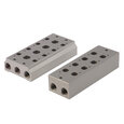
Pneumatic Manifold Working Principle
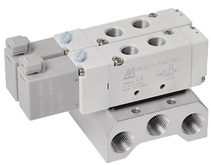
Figure 1: Pneumatic solenoid valves on a single piece design manifold
Pneumatic manifolds enable multiple pneumatic solenoid valves to utilize a single air supply and exhaust port, which greatly simplifies the system, reduces leakage, and lowers maintenance expenses. These air manifold blocks are crucial in settings that require numerous valves, such as mobile machinery and heavy industrial equipment. Manifolds come with various pressure ratings, port sizes, flow rates, and housing materials to meet specific requirements. They can also be tailored to specific brands or follow standardized mounting patterns. The reduced energy consumption due to shorter flow paths underscores the efficiency of manifolds. This article delves into the functionality and advantages of pneumatic valve manifolds in different applications.
Table of contents
- Types of pneumatic manifolds
- Blanking plates
- Standards
- Selection criteria
- Pneumatic manifold symbol
- FAQs
View our online selection of Pneumatic Manifolds!
Types of pneumatic manifolds
Solenoid valve manifolds fall into two general categories: single piece design (Figure 2) and modular block design. The single piece design can accommodate a specific number of valves with pre-determined port geometries. On the other hand, a modular block design is more customizable. It consists of single blocks that usually support one valve, and assembling individual blocks creates the manifold.
Single piece manifolds
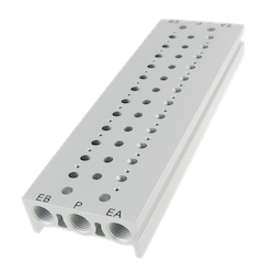
Figure 2: Single piece manifold
A single piece pneumatic manifold channels compressed air from a single input to multiple outputs (actuators, control valves, etc.) through the ports integrated within the manifold. The air is distributed evenly to all connected components, enabling coordinated operation of the pneumatic system.
The most common single piece manifold design is a steel, aluminum, cast iron, or plastic block with holes drilled to create the flow paths and ports. Due to their single-piece design, these manifolds are robust and can handle high-pressure applications. Typically, 2-10 pneumatic solenoid valves can be mounted on a single piece manifold. They need to be specified for how many ports (for example, for a 3/2-way or 5/2-way valve) and how many valves. Blanking plates (see below) are available to close off unused ports.
Modular manifolds
Modular block manifolds (Figure 3) are designed for adaptability. A single block of a modular manifold holds one valve. Blocks can be added or removed from the manifold for modification and maintenance. Due to their modularity, additional leakage paths are present in modular manifolds. Each connection point is sealed with an o-ring to mitigate leakage. Beyond the basic building blocks, a modular block manifold can also consist of interconnecting, divider, and spacer plates. Plates are typically installed between individual blocks, and the different plate types serve different purposes.
- Interconnecting plate: Interconnecting plates can divert flow between the different blocks.
- Divider plates: Divider plates block a flow path.
- Spacer plate: Spacer plates adjust the space between the blocks when a larger valve is used, requiring more space.
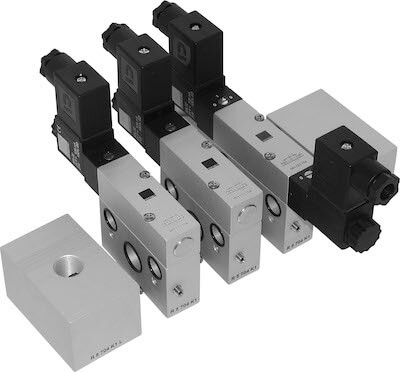
Figure 3: A disassembled modular manifold design
Blanking plates
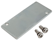
Figure 4: Blanking plate
If a pneumatic manifold block has more ports than solenoid valves, a blanking plate (Figure 4) is required to close off any unused ports. A blanking plate is easily secured into place and ensures that air does not leak out through the unused ports. Blanking plates are brand-specific or adhere to ISO 5599 or ISO 15407 standards.
Standards
Air manifold blocks that allow the interchangeability of valves from various manufacturers are designed according to ISO-standardized interfaces. These standards specify the dimensions of valve ports, mounting interfaces, and required electrical connections.
ISO 5599
ISO 5599 specifies the requirements for the mounting interface surface for five port pneumatic directional control valves for use at a maximum rated pressure of 1.6 MPa (16 bar). It gives dimensions and tolerances of the interface features, port identification, and identification of the result of control-mechanism actuation.
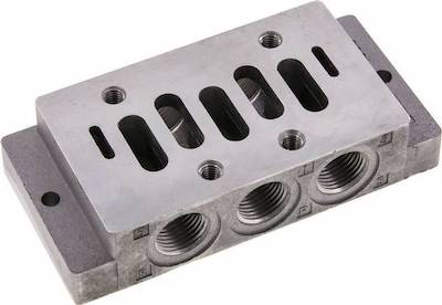
Figure 5: An example of an ISO 5599 manifold
ISO 1, 2, 3, & 4
Within the ISO 5599 standard are sizes 1, 2, 3, and 4. Valves and manifolds are often labeled ISO 5599-1 (or 2/3/4). These numbers correspond to the valve size (1 being the smallest). Therefore, the manifold must match the corresponding ISO number to mount the valve properly.
- ISO 1: 42 mm width
- ISO 2: 52 mm width
- ISO 3: 65 mm width
- ISO 4: 76 mm width
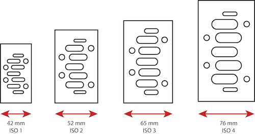
Figure 6: ISO 5599 sizes for ISO 1, 2, 3, and 4
ISO 15407
ISO 15407 specifies dimensions and tolerances of:
- Interface features
- Port identification
- Identification of the result of control-mechanism actuation
- Dimensions
- Tolerance
- Specifications for the mounting interface
- Specifications for the electrical connector
- For five-port pneumatic directional control valves, 18 mm and 26 mm
- For use at a maximum rated pressure of 1.6 MPa (16 bar).
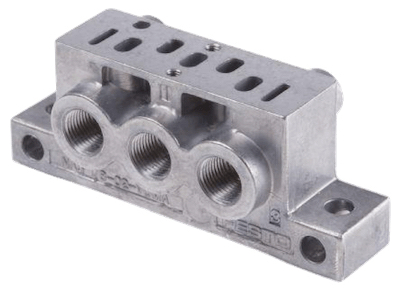
Figure 7: An example of an ISO 15407 manifold
ISO 01 & 02
Within the ISO 15407 standard are sizes 01 and 02. Valves and manifolds are often labeled ISO 15407-01 (or 02). These numbers correspond to the valve size (02 being the smallest). Therefore, the manifold must match the corresponding 01 or 02 to mount the valve properly.
- ISO 01: 26 mm width
- ISO 02: 18 mm width
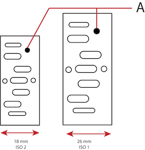
Figure 8: ISO 15407 sizes for ISO 02 and 01—hole for coding pin (A), which ensures correct alignment and assembly of manifold components.
Selection criteria
The main selection criteria of a pneumatic manifold are:
- Number of valve stations: A single piece design manifold with a set number of valve stations is a good solution if there is a set number of valves. A modular design is preferable if the number is unknown or could change.
- Number of valve ports: The number of the valve's ports must match the number of the manifold's ports.
-
Material: Pneumatic manifolds are typically made of stainless steel, aluminum, or plastic. The following criteria typically control which material is best for an application.
- Application environment: A stainless steel pneumatic manifold is best for corrosive or high-temperature environments as it's resistant to rust and heat. Aluminum is suitable for general-purpose applications and is known for its good heat dissipation properties. Plastic manifolds can be used where corrosion resistance is necessary, but the temperature and pressure are low.
- Pressure requirements: Stainless steel and aluminum manifold blocks can withstand higher pressure than plastic ones.
- Durability: Stainless steel is the most durable, followed by aluminum. A plastic pneumatic manifold is less durable but could be advantageous when weight is a concern.
- Cost: Plastic manifolds are generally less expensive than their metal counterparts.
- Maintenance: Stainless steel and aluminum are easier to maintain and have longer life spans compared to plastic.
- Mounting: Ensure that the manifold is either brand-specific mounting or adheres to the correct ISO standard and corresponding size.
Pneumatic manifold symbol
A pneumatic manifold symbol, as seen in Figure 9, is a perpendicular intersection of two lines inside of a square. The lines show that there are multiple connection points.

Figure 9: A pneumatic manifold symbol
FAQs
What is a pneumatic manifold?
A pneumatic manifold routes a single air supply to multiple pneumatic solenoid valves, also allowing them to be installed next to each other to conserve space.
What are the different types of manifold blocks?
The two types of manifold blocks are single piece and modular. Single piece blocks have a set number of ports, whereas modular blocks can be changed to fit changing system needs.


