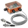
Water Pressure Sensor
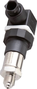
Figure 1: A water pressure sensor
Water pressure sensors measure water pressure through components like pipes, hoses, and tanks for various water applications. These sensors convert physical pressure into an electrical signal that is then converted into a digital value to be stored or displayed on an external display. These sensors are used in various applications, such as municipal water supply systems, irrigation, industrial process control, pump control, tank level monitoring, HVAC systems, and marine applications. The selection of a suitable sensor depends on multiple factors, including pressure and temperature range, accuracy, material compatibility, size and installation ease, output type, and cost.
Table of contents
- Working principle
- Water pressure sensor in a tank
- Water pressure sensor in a pipe
- Applications
- Selection criteria
- FAQs
View our online selection of water pressure sensors!
Working principle
A water pressure sensor, also known as a water pressure transducer, is a device that measures the water pressure and converts the measurement into an electrical signal. This electrical signal can then display, record, or control the pressure.
The working principle of a water pressure sensor is relatively straightforward and can be broken down into three main steps.
- Pressure measurement: The sensor measures water pressure by detecting the force that the water exerts on a specific area. This is usually done using a diaphragm or a pressure-sensitive element, such as a piezoelectric crystal or a strain gauge. When the water pressure changes, it causes the diaphragm or pressure-sensitive element to deform or change shape.
- Conversion to electrical signal: The diaphragm's or pressure-sensitive element's deformation or change in shape is then converted into an electrical signal. This is typically done using a Wheatstone bridge circuit, which can measure the change in resistance caused by the deformation. In a piezoelectric crystal, the deformation generates a voltage, which can be measured directly.
- Signal processing: The electrical signal is then processed and converted into a format that can be easily read and understood. This might involve amplifying the signal, filtering out any noise, and converting it into a digital signal if necessary. The processed signal can then display the pressure on a gauge and record it for later
Note:Some sensors provide zero-based outputs (e.g., 0 - 5 V), while others provide non-zero-based outputs (e.g., 1 - 5 V). The disadvantage of a zero-based output is a 0 reading can indicate zero pressure or that the sensor has failed. A zero reading on a non-zero output indicates failure.
Pressure options
A water pressure sensor can measure absolute, gauge, or differential pressure:
-
Absolute: Absolute pressure measurements are taken against zero pressure, irrespective of the atmospheric pressure. This is important for applications that may go below the atmospheric pressure or applications sealed from the atmosphere.
Underwater pressure sensor: The atmospheric pressure can change significantly deep underwater. An absolute pressure measurement indicates the pressure the water exerts despite the changing atmospheric pressure.
Gauge: Gauge pressure measurements are taken against the atmospheric pressure. These measurements are useful for applications that rely on atmospheric pressure, such as plumbing and water supply systems.
Differential pressure: Differential pressure measurements indicate the pressure difference between two different bodies of water. This type of measurement is used to measure pressure drops across filters or restrictions.
Read our pressure types article for more details on the differences between the types of pressure and the pressure gauges used to measure them.
Water pressure sensor in a tank
When a water pressure sensor is used to measure the pressure in a tank, the water level can also be determined using Pascal's Law. In other words, water pressure (P) is equal to the water's density (⍴) multiplied by the force of gravity (g) on the water multiplied by the height of the water column (h). Or:
Water pressure sensors in a tank are typically installed in one of two places, as seen in Figure 2:
Inside tank (A): A water pressure sensor in a tank is installed on top of an open-ended tube. As water rises in the tube, the air pressure changes, which the sensor can track.
At outlet (B): If the tank outlet connects to a horizontal pipe, a water pressure sensor can be installed on the pipe between the outlet and a stop valve (e.g., ball valve).
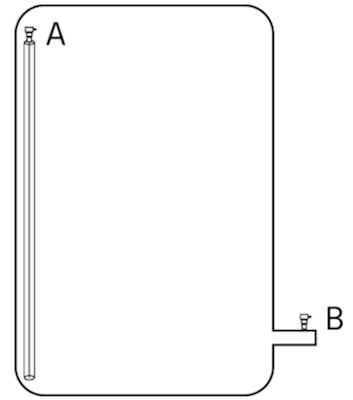
Figure 2: A water pressure sensor in a tank is typically installed at the top of an open-ended tube (A) within the tank or on a horizontal pipe at the tank outlet (B).
Water pressure sensor in a pipe
Water differential pressure sensors (Figure 3 labeled A) can measure the flow rate in a pipe. These pressure sensors measure the change in pressure across a restriction in the pipe (e.g., orifice or venturi) (Figure 3 labeled D). When water flows through the restriction, its velocity increases, and pressure drops. To measure flow rate, a simplified version of Bournelli's Principle is used:
Where:
P1 & P2: Upstream and downstream pressure
⍴: Fluid density (water = 1 g/cm3)
v1 & v2: Upstream and downstream velocities
According to the principle, the change in pressure equals the change in kinetic energy. So, with pressure change and fluid density data, the change in velocity across the restriction can be calculated, which is proportional to the flow rate (Q = A * v). For example, if the velocity doubles, the flow rate also doubles.
3 valve manifold
Water pressure sensors typically use a 3-valve manifold (Figure 3 labeled B) when connecting to a pipe. A 3-valve consists of two shut-off valves that isolate the pressure sensor from the process and a third equalizing valve that connects the two shut-off valves. When the equalizing valve is opened, the pressure between the low and high-pressure shut-off valves equalizes.
Isolation: Isolating the sensor from the pipe allows for easier maintenance, calibration, and replacement. The water flow to the sensor can be shut off without shutting down the entire system.
Safety: The 3-valve manifold also ensures that the water pressure in the pipe cannot damage the water sensor during installation or removal.
Pressure balance: The equalizer valve in the 3-valve manifold balances pressure on the high and low-pressure sides. This allows the water pressure sensor to be zeroed out for calibration purposes.
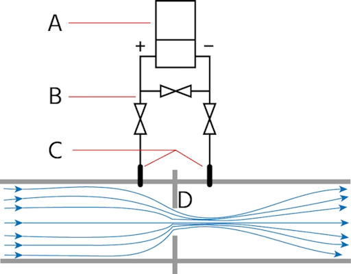
Figure 3: A differential pressure transducer (A) has two connection points (C) to the pipe on each side of a restriction (D). A 3-valve manifold (B) protects the sensor if the pressure in the pipe is too high.
Applications
Plumbing and HVAC systems: Water pressure sensors are used in residential, commercial, and industrial settings to monitor and control water pressure in plumbing and heating, ventilation, and air conditioning systems.
Irrigation and pump systems: These sensors ensure adequate water pressure for agricultural irrigation, garden watering systems, and various pump operations.
Industrial processes and treatment plants: They are utilized in various industries like chemical, pharmaceutical, and food and beverage for process control and automation, as well as in water treatment plants for monitoring and controlling water pressure during purification and distribution processes.
Marine and oil & gas industry: They monitor systems on ships and submarines and are used to monitor the pressure of water injection systems in the oil and gas industry.
Fire suppression and leak detection systems: These sensors monitor the pressure in fire sprinkler systems and detect and locate leaks in pipes and tanks.
Power plants and water supply networks: They control water flow and pressure in hydroelectric power turbines and monitor and control water pressure in municipal water supply systems.
Pool and spa equipment: They ensure proper water flow and filtration in pool and spa systems.
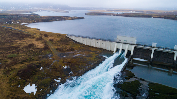
Figure 4: Water pressure sensors are essential in hydropower plants.
Selection criteria
Size and installation: The sensor should fit within the application's physical constraints and be easy to install and maintain.
Output signal: The sensor's output signal should be compatible with the control system that will be receiving the signal. Common output signals include 4-20mA, 0-10V, 0-5V, or digital outputs like RS485 or CAN bus.
Media compatibility: The sensor should be compatible with the liquid or gas that it will be in contact with. This includes the sensor's construction materials, such as the diaphragm and seals.
Range: The pressure range of the sensor should be appropriate for the maximum and minimum pressures that will be experienced in the application.
-
Accuracy: The sensor should be able to measure pressure with an accuracy suitable for the application. This includes considerations for linearity, hysteresis, and repeatability.
Linearity: As pressure changes, the sensor's output increases or decreases in a straight line. If it doesn't, there's a linearity error.
Hysteresis: The sensor's current output depends on its past outputs. If the reading is different when pressure increases compared to when it decreases, that's a hysteresis error.
Repeatability: The sensor's ability to give the same output for the same pressure, no matter how many times it's measured. High repeatability means the sensor is consistent and reliable.
Operating environment: The sensor should be able to operate effectively in the expected temperature and humidity conditions. It should also be able to withstand any potential vibration, shock, or electromagnetic interference.
Certifications: Depending on the application, the sensor might need specific certifications, such as those for use in hazardous locations or for drinking water applications.
Cost: Finally, the price of the sensor should fit within the budget for the project, taking into account not just the initial cost, but the total cost of ownership, including maintenance and potential replacement costs.
FAQs
How does a water pressure sensor work?
A water pressure sensor has an element (e.g., diaphragm) that deforms when water pressure changes. The deformation sends an electric signal to a converter to display the water pressure.
What's the difference between a water pressure sensor and a water pressure sensor switch?
A water pressure sensor records water pressure continuously and can be used to control a process. A switch, however, is primarily designed to control a process under specific pressure conditions.


