


Proportional Solenoid Control Valve Explained
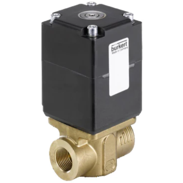
Figure 1: Proportional solenoid control valve
A proportional solenoid control valve is a device designed to manage the flow rate of a fluid by adjusting the size of the passage through which the fluid flows, using a restrictor. By regulating the flow rate, this valve influences key process parameters within a system, such as level, pressure, and temperature. Additionally, it can also affect other parameters like weight, thickness, humidity, density, pH, color, and viscosity.
In an automatic control valve, the restrictor is directed by a signal from a controller called an actuator. A proportional control solenoid valve utilizes a solenoid as an actuator for variable valve positioning.
View our selection of proportional solenoid valves!
Operating principle
A direct-operated 2-way standard proportional solenoid valve operates very similar to a direct-operated solenoid valve with the difference that the former operates through a range of valve positioning while the later only provides two switching states (i.e. on/off), Figure 2. In a direct-operated proportional solenoid valve, the plunger is the restrictor.
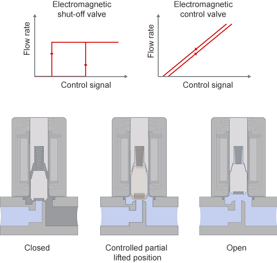
Figure 2: Functional Principle of direct-acting Solenoid Control Valves
In principle it is possible to proportionally control the plunger with variable DC voltage, however in practice static friction on the guide points of the plunger impairs the sensitivity of the valve, which results in greater hysteresis effects (the phenomenon in which the value of a physical property lags behind changes in the effect causing it). To prevent static friction, the normal inlet signal can be converted into a pulse width modulated voltage signal (PWM) using special control electronics.
Pulse-width modulation (PWM) is a technique often used to allow the control of the power supplied to electrical devices. The average value of voltage (and current) fed to the solenoid is controlled by turning the power switch on and off at a fast rate (Figure 3). This kind of control puts the plunger into a very fast but weak amplitude oscillation. The oscillation puts the plunger in a balanced state which maintains its constant sliding friction. The plunger’s oscillation motion has no effect on the fluid’s flow behavior.
The longer the switch is on compared to the off periods, the higher the total power supplied to the solenoid. The term duty cycle describes the proportion of on time, t1, to the cycle duration, T. A low duty cycle corresponds to low power, because the power is off for most of the time. Duty cycle is expressed in percent, 100% being fully on.
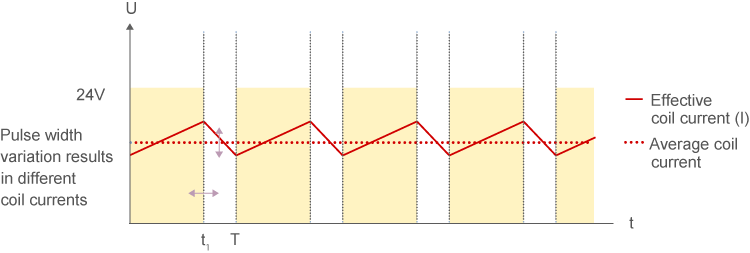
Figure 3: PWM Control Signal
In a normally closed solenoid control valve, with zero current fed to the coil, the spring pushes the plunger downwards to a fully closed position, therefore the valve in maintained close. Applying current to the coil generates a magnetic field to move the plunger upward against the return spring. At 100% duty cycle, power is fully fed to the solenoid and the valve is maintained open. Duty cycles between 0 to 100 percent range proportionally change the flow of the valve. For example, a duty cycle of 50% fed to the solenoid moves the spring and the plunger to 50% of the operating range.
Selection criteria
In Continuous flow applications, the choice of appropriate valve size is much more important than with on/off valves. With a high orifice setting the valve can already reach full flow rate at a very small opening (stroke). The remaining stroke is then useless, which impairs resolution and the general control quality of the valve. With an orifice size that is too small on the other hand, the valve won’t reach full flow rate. It is recommended that the pressure drop over the valve should be around 30 % of the total pressure drop within the system.
For correct and accurate control functioning, solenoid control valves must be configured and selected according to their special purpose. The most important parameters for selecting a solenoid control valve are, the kV value (given in m3/h) and the application’s pressure range. The lower the valve’s orifice or the stronger the coil, the higher the pressure the valve can shut-off. The highest kV value needed is calculated based on sizing formulas in Figure 4.
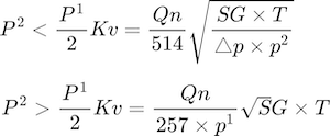
Figure 4: where:
QN= Normal Flow rate [m3/hour]
Kv = Hydraulic factor
T = Inlet gas temperature [K]
p1 = Inlet Pressure [bar]
p2 = Outlet Pressure [bar]
dp = Pressure differential [bar]
SG = Specific Gravity (Air = 1)
Based on the calculated kV value and the pressure range of the planned application, a correspondingly appropriate valve type and its required orifice can be determined. Please note that the valve’s kVs should be greater than the application’s kV ideally by approximately 10 %.
Other selection criteria to be considered are maximum operating pressure, media (fluid), power consumption, compatibility of materials, response time, media temperature, operating voltage, and port connection to name a few. For more information regarding these selection criteria please refer to this article, or manufacturer’s datasheet for the specific product.
Typical applications
Here are some common applications of Proportional Solenoid Control Valve.
- Burner/Flame Control: Two gases must be controlled in a burner control system; both are in a desired ratio with one another. The ratio of combustion gas to oxidant gas, e. g., air or oxygen, is determined by the flame that is required for the respective process.
- Level Control with Pressurization (Flow Pressure Control): Atmospheric pressure control is one possible type of level control. Via two solenoid control valves, a PID controller supplies enough air or nitrogen so that there is always the same pressure pressing against the fluid that changes when the fluid pressure drops through removing a portion of the fluid.
- Mixture of Cold and Warm Water: A Pt100 temperature sensor measures the temperature of the mixed water. The temperature controller brings this temperature to the given reference value by controlling two solenoid control valves accordingly.
- Temperature Control: A solenoid control valve can set the cold water supply to a heat exchanger in accordance with the measured process water temperature. If this is higher than the reference value, more cold water is required. If it is lower than the reference value, less cooling is required. A heating circuit works in a similar way.
-
Flow Control: A solenoid control valve can be used directly as a control valve, for direct flow control, for example.
Actuator Control (Static Pressure Control): Two solenoid control valves can control the air for pneumatic drive (piston valve, cylinder, etc.). A PID controller determines which of the two valves must open. The control electronics set the drive via the solenoid control valves so that the process value corresponds with the set point given. - Ejectors/Pressure Control: A solenoid control valve can control the propellant gas flow rate. More propellant gas creates greater suction power and a deeper vacuum in the suction line. The controller sets the valve according to the vacuum pressure.

