3/2-Way Pneumatic Solenoid Valve Overview

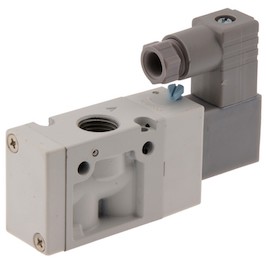
Figure 1: A 3/2-way pneumatic solenoid valve
3/2-way pneumatic solenoid valves are essential for regulating air flow in a variety of applications, including single-acting cylinders, pneumatic actuators, and tasks such as blow-off, pressure release, and vacuum operations. This article provides an overview to help readers better understand general 3/2-way pneumatic solenoid valve topics, including applications, working principles, and more.
Table of contents
- Design of 3/2-way valves
- Circuit function of 3-way air valves
- How does a 3/2-way pneumatic solenoid valve work?
- Applications
- Versatility and environmental considerations
- FAQs
View our online selection of 3/2-way pneumatic solenoid valves!
3/2-way vs 2/2-way & 5/2-way
3/2-way pneumatic solenoid valves have an inlet port, an outlet port, and an exhaust port. They are used to control simpler pneumatic systems (e.g., single-acting pneumatic cylinders) with the added benefit of exhaust. Whereas 2/2-way pneumatic solenoid valves are used for simple on/off control and 5/2-way pneumatic solenoid valves are used for controlling double-acting pneumatic cylinders. 5/2-way valves can control the air supply in both chambers of the double-acting solenoid valve.
Design of 3/2-way valves
3/2-way pneumatic solenoid valves come in various designs and can be categorized based on their operation and stability.
Based on operation
- Direct operation: Direct-operated valves only use the solenoid to open or close without a need for pressure in the system.
- Indirect operation: In indirectly operated valves, the spool is not directly actuated by the solenoid. Instead, the system pressure moves the spool. This requires an additional pilot valve, a small, direct-operated 3/2-way valve. The pilot valve delivers compressed air to a small air cylinder inside the valve, pushing against a piston to actuate the solenoid and switch the valve. This allows for the use of a relatively small solenoid to switch the valve.
Based on stability
- Monostable valves: Monostable valves return to their default position using spring force. They typically have one coil.
- Bistable valves: Bistable valves have a coil at each position and are pulse-operated. They can maintain their position without the need for continuous power, switching between two stable states. Learn more in our article on latching solenoid valves.
Circuit function of pneumatic 3/2 way pneumatic solenoid valve
The 3/2-way pneumatic valve, also known as an air-actuated valve, has three connection ports and two states. The ports are:
- Inlet (P, 1)
- Outlet (A, 2)
- Exhaust (R, 3)
The valve has two states: open and closed. When the valve is open, air flows from the inlet (P, 1) to the outlet (A, 2). When the valve is closed, air flows from the outlet (A, 2) to the exhaust (R, 3). A valve that is closed in its non-actuated state is called a normally closed (NC) valve, while one that is open in its non-actuated state is called a normally open (NO) valve.

Figure 2: Circuit function of a mono stable, normally closed, 3/2-way valve
Most 3 way solenoid valves are monostable and return to their default position when not actuated, typically using a spring mechanism. Bistable 3/2 pneumatic solenoid valves retain their position during power loss and require a separate action to switch states. So, bistable valves cannot be called NC or NO.
In summary, the different functions of the 3/2-way valve are:
- 3/2-way monostable NC
- 3/2-way monostable NO
- 3/2-way bistable
The circuit functions are represented using valve and pneumatic symbols. Figure 3 shows the symbols of an indirectly operated 3/2 solenoid valve. Learn about other pneumatic valve symbols and their explanation in our valve symbol article.

Figure 3: Symbols of 3/2-way indirectly operated pneumatic solenoid valves, from top to bottom: normally open mono stable, normally closed mono stable, bistable.
How does a 3/2-way pneumatic solenoid valve work?

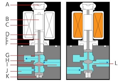
Figure 4: Solenoid-operated 3/2-way pneumatic valve design in the closed (left) an open (right) states: Manual operator (A), fixed core (B), solenoid (C), armature (D), push pin (E), return spring 1 (F), spool (G), atmosphere (H), valve output (I), air supply (J), return spring 2 (K), and orifice (L).
In a solenoid-operated 3/2-way pneumatic valve, the main components and their functions are:
- Manual operator (A): Allows for manual control of the valve.
- Fixed core (B): Provides a stationary magnetic core for the solenoid.
- Solenoid (C): Generates a magnetic field to move the armature.
- Armature (D): Moves in response to the magnetic field generated by the solenoid.
- Push pin (E): Transfers the movement of the armature to the spool.
- Return spring 1 (F): Returns the armature to its default position when the solenoid is de-energized.
- Spool (G): Controls the flow of air through the valve.
- Atmosphere (H): The exhaust port where air is released.
- Valve output (I): The port through which the media exits the valve.
- Air supply (J): The port where compressed air enters the valve.
- Return spring 2 (K): Assists in returning the spool to its default position.
- Orifice (L): The opening through which air flows within the valve.
Applications
3/2-way valves are suitable for various tasks, including driving pneumatic actuators, blow-off, pressure release, and vacuum applications.
Controlling a single-acting cylinder
A single-acting cylinder has one pneumatic port for filling and emptying the air chamber. The cylinder moves in one direction when the air chamber is filled and returns to its original position due to the spring force. The 3/2-way valve either fills the air chamber or vents it to the atmosphere. Figure 5 shows a basic pneumatic circuit for a single-acting cylinder.

Figure 5: Schematic representation of a single-acting cylinder drive with a 3/2-way valve
Blow off, pressure release, and vacuum applications
3/2-way pneumatic solenoid valves are ideal for blow-off, pressure release, and vacuum applications. Externally piloted or direct-actuated valves are often necessary because they do not require a minimum pressure differential. Figure 6 shows blow-off, pressure release, and vacuum valve configurations.
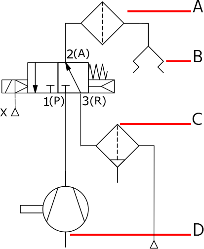
In the vacuum circuit, the vacuum pump is connected to port (P, 1), and atmospheric pressure is connected to port (R, 3). The vacuum is broken when port (A, 2) is connected to port (R, 3). The vacuum pad picks up the object when the vacuum pump (connected to port P, 1) is switched on.

Figure 6: From top to bottom, configurations for externally piloted: blow off, pressure release, and vacuum applications.

Figure 7: Valve symbol of a 3/2-way valve used for a vacuum application: Vacuum filter (A), vacuum pad (B), filter with separator, manual drain (C), vacuum pump (D)
Versatility and environmental considerations
With a NAMUR housing, the valve can be directly mounted to an actuator that also meets the NAMUR standard. Manifolds can be used to save space and group valves. Multiple 3/2-way valves can be built into one manifold, and it is possible to mix valve types, such as mounting a 5/2-way valve next to a 3/2-way valve. The combinations depend on the manifold's type and design.
Environmental considerations are crucial in pneumatic systems. Valves and seals must be resistant to corrosion when exposed to aggressive substances. Special valves are available for clean room areas, ATEX environments, and the food industry.
A 5/2-way valve can function as a 3/2-way valve by using only one inlet and the corresponding outlet port. Additionally, the function of a 3/2-way valve can be mimicked using two 2/2-way valves.
FAQs
How does a 3 way 2 position valve work?
A 3-way 2-position valve has three ports and two positions. It directs flow between two of the three ports in each position, allowing for control of fluid direction, typically used for diverting or mixing flows.
What is the difference between a 2-way and 3-way valve?
A 2-way valve is any type of valve with two ports: an inlet and an outlet port. A 3-way valve has three ports within the valve body which are used as inlet, outlet, and exhaust.


