Burkert 5282 Solenoid Valve - How They Work
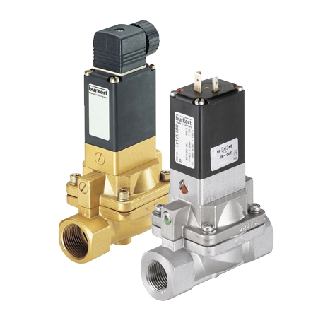
Figure 1: Bürkert 5282 solenoid valve
The Bürkert type 5282 valve is an all in one solenoid valve featuring indirect-operation, adjustable response time, manual override and medium separation which makes it suitable for aggressive or slightly contaminated media. This valve type also includes ATEX approved versions for use in potentially explosive atmospheres.
Various combinations of housing and membrane materials, the possibility to switch between NC and NO, and a variety of orifice sizes ranging from 13 to 65 mm give you the flexibility to fit this servo-assisted diaphragm control valve to your application.
Table of contents
- Is Bürkert 5282 the right valve for you?
- Type 5282 solenoid valve for challenging applications
- Approvals for the 5282 valve
- Features
Is Bürkert 5282 the right valve for you?
The Bürkert 5282 is designed for reliability and durability and is therefore selected for tough circumstances. It is the many standard features of the 5282 that makes it stand out. This valve might be the right choice for your application if:
- Your medium is a fluid or a gas with a permanent pressure differential of at least 0.2 bar
- Your medium is clean or slightly contaminated
- It is desired to control the circuit behaviour by adjustable response times
- Your application demands relatively high flow rates
- You are looking for valves to be used in potentially explosive atmospheres
Type 5282 solenoid valve for challenging applications
Dust suppression, mineral processing, mining, hydraulics, chemical and fire industries all choose Bürkert type 5282 for its reliability and various options, specifications and certifications.
This electric diaphragm valve delivers large flow rates with Kv-values of up to 40 (almost 670 ), which is comparative to flow rates of larger servo-assisted valves. However, the internal construction is entirely different. This valve uses a 3/2-way pilot valve for the servo-assisted function, while a regular indirect operated valve uses a diaphragm hole and a 2/2-way pilot valve.
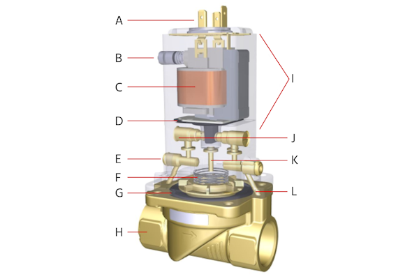
Figure 2: Burkert 5282 components: electrical connection (A), manual override (B), solenoid coil (C), isolating membrane (D), speed control (E), closing spring (F), diaphragm (G), valve housing (H), 3/2-way pilot valve type 0331 (I), upstream pilot port (J), connection to upper chamber (K), and downstream pilot port (L).
In a regular indirect operated (servo-assisted) valve, media flows in, filling the lower and upper reservoirs, reaching the plunger tube. When the valve is energised, media is allowed to drain from the upper reservoir, and the pressure built up at the bottom of the diaphragm forces it up and the valve opens. When the valve is de-energised, media passes through the diaphragm hole and fills the upper reservoir again. This small hole is crucial to the functionality of this type of valve and any particulate matter such as dirt, rust, calcium deposits can risk a blockage.
On the other hand, the 5282 valve is operated in a way that media is entirely isolated from the pilot assembly. The pilot in this type of valve is a 3/2 direct-acting pivoted armature solenoid valve. This pilot valve drains and fills the upper reservoir of this valve, without having any of the crucial parts to be in direct contact with media (Figure 3). The closing process is additionally supported by a stainless-steel compression spring. A minimal differential pressure between the inlet and outlet is needed for complete opening and closing.
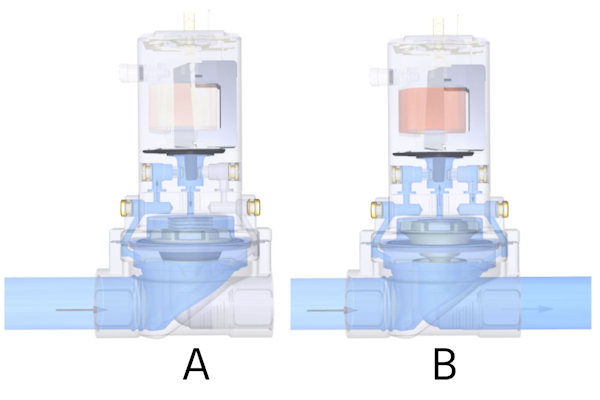
Figure 3: Operating principle: de-energized (A) and energized (B) states
The wetted parts of the Bürkert 5282 valves are made of high quality materials which are resistant to aggressive media. Flow paths are large enough to avoid blockage and are forgiving to particle contaminations. There are very few moving parts with only small movements to avoid wear.This valve is reliable, and reliability is the key to sustainability of the valve year after year.
Approvals for the 5282 valve
This valve series is available with a wide variety of approvals. The most important are listed below:
UL , UR: Underwriters Laboratories inspects and certifies products with respect to their safety
CSA: The Canadian Standard Organization
Ex (ATEX Cat. 2): ATEX covers devices and protective systems that will be used in explosion-prone areas (Europe)
KOSHA : Safety components, pressure containers and products for the Ex area must be approved by KOSHA in South Korea.
NEPSI : Explosion-protected electrical operating equipment are tested and certified by NEPSI in China.
CGA/AGA : The Australian Gas Association tests and certifies products and machines from the gas, electrical and sanitation areas.
KTW W270 : The KTW guideline is the approval of plastics and other non-metallic materials (e.g. sealing materials) for use with potable water in Germany. EAC: The EAC mark applies for products to be place on the market in Russia, Kazakhstan and Belarus.
Features
ATEX versions
Explosion proof versions of this valve type are suitable for potentially explosive environments. The ATEX ratings are:
II 2G Ex mb IIC Gb
II 2D Ex mb IIIC T130°C Db
II 2G Ex eb mb IIC T4 Gb
II 2D Ex mb tb IIIC T130°C Db
Port size range
The valve is available with port sizes from G ½“ up to G 2 ½“. The table below shows the corresponding orifice sizes and Kv-values. The Kv-value indicates the flow rate of water in m3 per hour with a pressure drop of 1 bar. Correct valve sizing is very important to guarantee good performance of your system and also to optimize costs. Use our valve sizing calculator to quickly determine the right valve size.
| Port size (BSP) | Orifice (mm) | Kv (m3/h) | Pressure (bar) |
| G 1/2" | 13 | 4 | 0.2-10 |
| G 3/4" | 20 | 6.5 | 0.2-10 |
| G 1" | 25 | 10 | 0.2-10 |
| G 1-1/4" | 32 | 20 | 0.2-10 |
| G 1-1/2" | 40 | 20 | 0.2-10 |
| G 2" | 50 | 40 | 0.2-10 |
| G 2-1/2" | 65 | 40 | 0.2-10 |
Material selection
The valve is available with housing materials made of brass, stainless steel and grey cast iron. The brass housing satisfies all European drinking water requirements.
Suggested media per seal material are as follows:
NBR: Neutral fluids such as compressed air, water, hydraulic oil
EPDM: Oil and fat-free fluid, e.g. alkaline solutions, hot water
FKM: Hot air, peracetic acid, hot oil
Adjustable circuit function
Convert the valve from the normally closed (NC) to the normally open (NO) function by simply rotating the pilot drive around by 180° (Figure 4). The pilot valve is the Bürkert type 0331 valve that can also be purchased separately. By loosening two bolts at the top of the coil, the pilot valve can be removed from the valve and installed back in reversed position. For detailed instructions, please refer to the manual which can be downloaded at the bottom of this article.
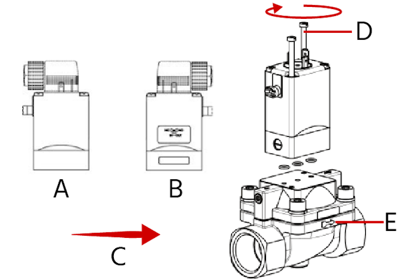
Figure 4: Adjustable circuit function to switch between NC and NO: NC (A), NO (B), flow direction (C), rotating torque should be less than 2Nm (D), and identification for flow direction (E).
To select the correct product please refer to the technical data, images and notes for proper use according to the data sheet.
Manual override
The valves have an manual override button on the side of the coil. This standard feature is very handy during commissioning, testing or maintenance. The override can be activated by pressing the button and rotating to lock it. Please note that the valve cannot be electrically actuated while the override is active.
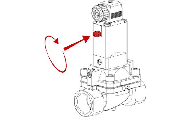
Figure 5: To use the manual override, first push and then rotate the button
Adjustable response times
Closing and opening times can be individually adjusted which can prevent water hammer (Figure 6). On both sides of the valve, the settings can be adjusted by rotating the screws with a screwdriver. To extend the response time, turn clockwise. To decrease the response time, turn anti-clockwise. Please note that the screws should never by unscrewed too far to prevent the media from flowing out. For detailed instructions on how to set response times, please refer to the manual at the bottom of this article.
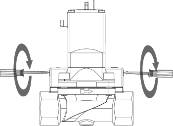
Figure 6: To adjust the response time, turn the screws to increase (clockwise) or decrease (anti-clockwise)


