


3/2-Way Pneumatic Solenoid Valves For Single-Acting Pneumatic Cylinders
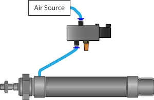
Figure 1: Pneumatic directional control valves mounted to a manifold.
A 3/2-way pneumatic solenoid valve controls compressed airflow to a single-acting pneumatic cylinder. The air overcomes the cylinder's spring force, either retracting or extending the piston rod. This depends on how the cylinder is constructed. 3/2-way pneumatic solenoid valves are used because they can direct air from the air source to the cylinder, and then from the cylinder through the exhaust. The combination of the pneumatic solenoid valve and cylinder is often used for material handling and packaging applications. Selecting the right 3/2-way solenoid valve is crucial for efficient and reliable pneumatic system performance.
Note: This article focuses only on selecting 3/2-way pneumatic solenoid valves for single-acting cylinders. Learn more about other configurations by reading our guide on single-acting vs double-acting pneumatic cylinders.
Table of contents
Selection criteria
1. Connection size and type
Selecting for connection size is typically simple because you must choose a size that matches what the pneumatic solenoid valve will connect to.
- BSPP: British Standard Pipe Parallel. Sometimes denoted with the letter G, e.g., G 1/4". The 1/4" refers to the inner diameter of the connection.
- Metric: Metric sizes are denoted with the letter M, e.g., M3 and M5. The number following the letter M denotes the major diameter in millimeters.
- QS: QS indicates a quick push-in connection for pneumatic tubing, e.g., QS-8 and QS-10. The number following QS indicates the outside diameter of the tubing for which the connection is suitable. For example, QS-8 means the connection is suitable for 8 mm pneumatic tubing.
- NPT: National Pipe Thread is a connection size typically used in the United States. The number following NPT, e.g., NPT 1/4", refers to the inner diameter of the connection.
- Flange: In the context of pneumatic solenoid valves, flange refers to a flanged NAMUR connection that makes the valve suitable for mounting to pneumatic quarter-turn actuators. The number following "Flange", e.g., Flange 1/4, refers to the size of the pneumatic ports on the flange.
- Sub-base: Sub-bases for pneumatic valves are a mounting base for installing and connecting multiple pneumatic solenoid valves. Sub-bases simplify and help organize pneumatic circuits that require multiple solenoid valves. Sub-bases have mounting holes and air passages, allowing for easy installation and efficient air distribution.
2. Function
- Normally open (NO): Figure 2 top. Air flows from port 1/P to port 2/A when the solenoid is not actuated. When the solenoid is energized, air is vented from port 2/A to port 3/R. Upon deactivation, a spring returns the valve to the open position.
-
Normally closed (NC): Figure 2 center. When not actuated, the air is vented from port 2/A to port 3/R. When the solenoid is energized, airflows from port 1/P to port 2/A. Upon deactivation, a spring returns the valve to the closed position.
- NC vs NO: What state should the pneumatic cylinder have if power is lost. Should the rod be extended or retracted? Consider these questions when selecting the pneumatic solenoid valve for your specific cylinder.
- Monostable: Monostable valves require constant energy to move the spool from its default position. Upon deactivation, a spring returns the spool to its default position.
-
Bi-stable: Figure 2 bottom. A bi-stable valve changes its position when activated and maintains it when deactivated. There are two main types: latching and detent.
- Latching: The spool position is changed when the valve is energized and maintains its position when energy is switched off. It uses a permanent magnet to hold the spool in place.
- Detent: This uses a mechanical mechanism to hold the spool in place.
- Selecting between: Typically, latching mechanisms require less energy, and detent are more durable because their locking mechanism cannot be affected by magnetism.

Figure 2: Symbolic representation for 3/2-way solenoid valves: normally open & mono-stable (top), normally closed & mono-stable (center) and normally closed & bi-stable (bottom).
3. Voltage
Choosing the correct voltage for a pneumatic solenoid valve is simple because it needs to match the available power supply.
4. Material
Selecting material involves selecting the body material and the seal material. This is an important selection because the material must be compatible with the system's medium. Read our chemical resistance of materials guide to learn more.
Several materials are available for both body and seal. Different materials have different operational characteristics (e.g., pressure and temperature). Pay attention to these characteristics when making decisions.
5. Operation
The spool's or piston's movement can be controlled directly or indirectly:
- Direct operation: The solenoid directly actuates the spool, meaning these valves can operate at 0 bar/psi pressure.
- Indirect operation: The solenoid actuates a small pilot valve, which actuates the spool or piston. A smaller solenoid valve, requiring less energy, can control the pneumatic solenoid valve. Therefore, the system must have pressure for a pneumatic solenoid valve to operate indirectly. Additionally, indirect operation allows for higher flow rates.
6. Minimum pressure difference
As described in section 5, indirect operation pneumatic solenoid valves require a minimum pressure difference. This difference can range from 0.95 (i.e., vacuum) to 2 bar (13.77 to 29 psi).
7. Max pressure
Ensure the pneumatic solenoid valve's max pressure is high enough to operate the pneumatic cylinder efficiently. Values range from 7 to 12 bar (101 to 174 psi). Many single acting air cylinders have a pressure range of 0.4-2 to 10 or 12 bar. (5.8-29 to 174 psi).
Therefore, any pneumatic solenoid valve can operate the cylinder's minimum pressure range. Still, only valves with a max operating pressure of 10 or 12 bar can operate the cylinder at its maximum pressure range.
8. Features
- Energy efficient: Energy-efficient pneumatic solenoid valves require a nominal power of 9 VA or less. These are good solutions for saving energy, but may have lower maximum operating pressures. Therefore, they may not be able to operate single-acting cylinders at their max pressure range.
- Latching:Latching solenoid valves use a permanent magnet to hold the valve's position in place even when it is not energized, saving power.
- Manual override: Manual override is necessary in the event of a power outage.
- Lubricated air possible:Single-acting pneumatic cylinders require proper lubrication. One method to achieve proper lubrication is to use an FRL unit. In this situation, it's essential to ensure the pneumatic solenoid valve in the system can also be used with lubricated air.
9. Approvals
Approvals indicate that a device meets standards set by national and international organizations (ATEX and Underwriter's Laboratory). Single-acting pneumatic cylinders typically have ATEX and food-grade approvals. Pneumatic solenoid valves typically do not have food-grade approvals but do have ATEX approvals.
10. Kv value
The Kv value of a pneumatic solenoid valve indicates its flow capacity. It represents the air flow rate through the valve in cubic meters per hour (m³/h) at a pressure drop of 1 bar across the valve. The higher the Kv value, the greater the valve's flow capacity.
Kv values for pneumatic solenoid valves typically range between 1 to 4 m³/h. Low and high Kv values have different impacts on single-acting pneumatic cylinders.
- Low Kv: Low Kv values provide more precision over the extension and retraction of the cylinder's rod.
- High Kv: High Kv values can fill and operate the pneumatic cylinder faster and exhaust it faster.
11. Temperature range
To ensure compatibility, the pneumatic solenoid valve should have the same operating temperature range as the pneumatic cylinder. For example, single-acting round ISO 6432 cylinders have a temperature range of -20 to 80 °C (-4 to 176 °F). However, 3/2-way pneumatic solenoid valves have a max temperature range of 70 °C (158 °F).
This means the valves cannot operate at the cylinders' maximum temperature range. However, this should not be an issue if the system temperature will never exceed 70 °C.
12. Max flow rate
When the air consumption and the required airflow are calculated, the valve can be selected. The valve data sheets must be checked to find the appropriate valves. All data sheets contain information about the valves' flow rates.
Figure 3 provides an example. The flow rate of the selected valve needs to be higher than the system's required air flow.
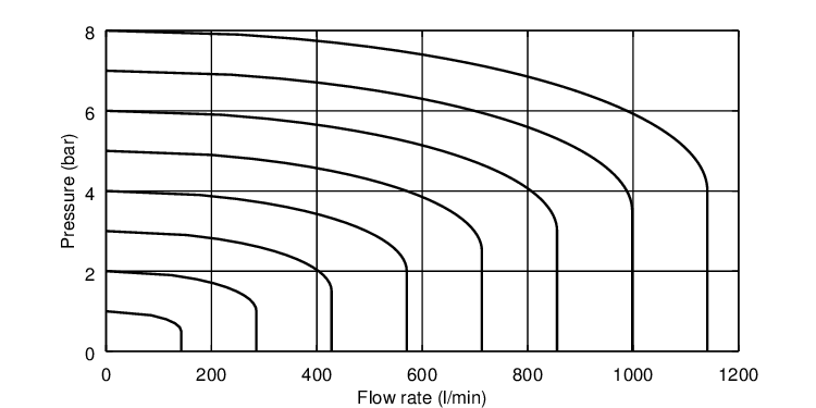
Figure 3: Example of a flow rate diagram with nominal flow rate (L/min) against inlet pressure and pressure loss.
FAQs
How does a single acting pneumatic cylinder work?
A single acting pneumatic cylinder uses air to extend or retract the piston and a spring to retract it to its default position. The compressed air is controlled by a pneumatic solenoid valve.
How do you control an air cylinder with a solenoid valve?
To control an air cylinder with a solenoid valve, connect the valve to the air source, exhaust, and cylinder. The valve alternates air supply and venting to move the piston.

