Hydraulic Floor Jack
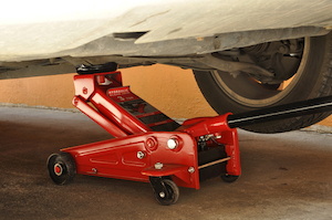
Figure 1: A hydraulic floor jack.
A hydraulic floor jack is used for lifting a heavy vehicle using little effort. Floor jacks can fit under vehicles with low clearance to lift them for maintenance or repair work on the undercarriage. This article fully explains hydraulic floor jacks: their key components, how they work, and how to use them. For a complete understanding of hydraulic jacks, read our hydraulic jack overview article.
Table of contents
- Hydraulic floor jack design
- Hydraulic floor jack operation principle
- How to use a hydraulic floor jack
- Hydraulic floor jack maintenance & repair
- Hydraulic floor jack vs bottle jack
View our online selection of hydraulic jacks!
Hydraulic floor jack design
A hydraulic floor jack’s design allows for lifting heavier loads than a bottle jack. Also, the body’s design allows a floor jack to position in lower clearance spaces easily. The part of the frame has two designs: straight (Figure 1) and curved (Figure 2). The curved frame allows for the jack’s saddle to go underneath vehicles that have significantly low clearance.
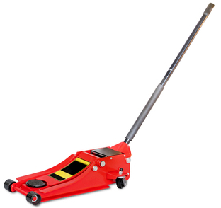
Figure 2: A hydraulic floor jack with a curved body. These jacks can access the underside of vehicles with exceptionally low clearance.
Hydraulic floor jack body material
Hydraulic floor jacks are made out of steel or aluminum. The material does not significantly impact the lifting capacity of the hydraulic jack.
- Steel: Steel hydraulic floor jacks weigh approximately 45 kg (100 lbs). They are heavier than aluminum, but the body can resist damage much better. Steel hydraulic floor jacks are ideal for staying in a garage.
- Aluminum: Aluminum floor jacks weigh approximately 27 kg (60 lbs). These jacks are more suitable than steel jacks for portability to different worksites. Aluminum floor jacks can handle most garage lifting tasks.
Hydraulic floor jack components
The key hydraulic floor jack parts are:
- Saddle/Bearing pad: The saddle, also known as the bearing pad (Figure 3 labeled A), contacts the vehicle’s lift point.
- Lifting arm: The lifting arm (Figure 3 labeled B) raises the saddle.
- Cover plate: The cover plate (Figure 3 labeled C) gives access to and protects the hydraulic components from foreign material.
- Socket: The socket (Figure 3 labeled D) operates the jack’s pistons by moving up and down.
- Leveling arm: The leveling arm (Figure 3 labeled E) provides extra support and stability to the lifting arm.
- Caster wheels: The caster wheels (Figure 3 labeled F) can rotate 360°, allowing for more mobility.
- Reservoir: The reservoir (Figure 3 labeled G) holds the hydraulic fluid and supplies it to the piston assemblage.
- Piston assemblage: The piston assemblage (Figure 3 labeled G) moves hydraulic fluid through the system to operate the lifting arm. There are two pistons: the plunger piston and the ram piston.
- Release valve: The release valve (Figure 3 labeled G) returns fluid to the reservoir to lower the saddle.
- Screw plug: The screw plug (Figure 3 labeled G) opens to allow a user to put more hydraulic fluid in the reservoir.
- Handle: The handle (Figure 3 labeled H) fits into the socket to move it up and down and operate the piston assemblage.
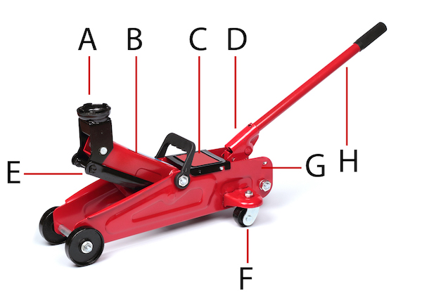
Figure 3: The components of a hydraulic floor jack are saddle/bearing pad (A), lifting arm (B), cover plate (C), socket (D), leveling arm (E), caster wheels (F), and handle (H). Components not seen in this image, below the socket, are piston assemblage, release valve, reservoir, and screw plug (G).
Hydraulic floor jack operation principle
Pascal’s Law defines how a hydraulic floor jack uses force multiplication to easily lift heavy loads. According to Pascal’s Law, pressure is equal to force divided by area (P = F/A). In the case of a hydraulic floor jack, area refers to the diameter of the two pistons; the plunger piston is narrower than the ram piston.
Figure 4 is a simple diagram of the hydraulic system in a hydraulic floor jack. When the handle (Figure 4 labeled F) moves the socket up, the plunger piston (Figure 4 labeled E) moves backward and siphons hydraulic fluid from the reservoir (Figure 4 labeled G) into the plunger cylinder. When the handle moves the socket down, the plunger piston moves forward and pushes the hydraulic fluid into the ram cylinder (Figure 4 labeled A). A check valve (Figure 4 labeled D) stops hydraulic fluid from flowing from the ram cylinder to the plunger cylinder. As a user pumps the handle, more and more fluid builds up in the ram cylinder, building the pressure and raising the bearing pad (Figure 4 labeled B).
To release pressure in the ram cylinder, a user turns the release valve, which opens the check valve (Figure 4 labeled D) between the ram cylinder and the reservoir. Hydraulic fluid flows back into the reservoir, and the saddle lowers.
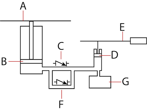
Figure 4: A simple diagram of the hydraulic components in a hydraulic floor jack: ram piston in ram cylinder (A), saddle/bearing pad (B), check valve between ram cylinder and plunger cylinder (C), check valve between ram cylinder and reservoir (D), plunger piston in plunger cylinder (E), handle (F), and reservoir (G).
How to use a hydraulic floor jack
There are three phases of using a hydraulic floor jack. Each phase has steps that should not be skipped.
Before
- Check the hydraulic floor jack for any damage or leaking.
- Ensure the vehicle is level.
- Block the wheels on the side of the vehicle that will not raise.
- Put jack stands close to the work site so they are easily accessible.
- Determine the vehicle’s lift points by reading the vehicle’s manual.
During
- Insert the handle into the hydraulic jack’s socket.
- Use the handle to move the hydraulic floor jack into position.
- The bearing pad should be approximately under a lift point; perfect precision is not necessary at this point.
- Pump the handle to raise the bearing pad. When the bearing pad is a few centimeters away from the lift point, reposition the hydraulic jack so the bearing pad will contact the lift point evenly.
- Lift the vehicle as much as necessary for the particular job.
- Position a jack stand next to the hydraulic jack under a lift point.
- Slowly lower the bearing pad so that the weight of the vehicle goes on the jack stand. Then fully lower the jack and remove it from under the vehicle.
After
- Use the hydraulic floor jack to lift the vehicle off the jack stand.
- Remove the jack stand from underneath the vehicle.
- Slowly lower the vehicle.
Hydraulic floor jack maintenance & repair
Hydraulic floor jacks require preventative care, maintenance, and perhaps repair. These jacks require proper storage, inspection, cleaning, bleeding, and oil checks. Learn more about these techniques by reading our hydraulic jack maintenance and repair article.
Hydraulic floor jack vs bottle jack
A bottle jack is an alternative hydraulic jack that has a vertical piston to lift straight up, as opposed to a floor jack’s horizontal piston. Floor jacks have the following advantages over bottle jacks:
- Maneuverability: Because they have wheels, floor jacks are easier to move around on a level surface.
- Lift: Hydraulic floor jacks can lift vehicles higher than bottle jacks can.
- Clearance: Hydraulic floor jacks are easier to position under vehicles, especially those with low clearance underneath.
- Weight: Floor jacks can lift more weight than bottle jacks.
A bottle jack is lighter and more compact than a floor jack, making it easier to store. Also, bottle jacks are less expensive than floor jacks. Learn more by reading our bottle jack article. Read our hydraulic jack applications for more details on the appliactions of floor and bottle jacks.


