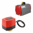
Pneumatic Rack-and-Pinion Actuators
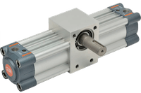
Figure 1: Rack-and-pinion rotary actuator
Rack-and-pinion pneumatic actuators, also known as limited rotation cylinders, are rotary devices used for various mechanical functions such as turning, opening, closing, mixing, oscillating, positioning, and steering, all involving restricted rotation. These actuators are frequently employed to automate quarter-turn valves, including ball and butterfly valves. They convert the energy from compressed air into an oscillating rotary motion using a pneumatic cylinder. The necessary clean, dry, and processed gas for these actuators is supplied by a central compressed air station, which typically supports multiple pneumatic devices within a process system.
Pneumatic actuators, in comparison to their electric counter parts, are generally more durable, better suited for hazardous environments and less expensive. In addition, they often require less maintenance and provide higher torque in comparison to their size. Read our article on Festo's pneumatic semi-rotary drives to learn about a specific rack-and-pinion drive.
Table of contents
View our online selection of pneumatic rotary actuators!
Design
In a pneumatic rack-and-pinion actuator, the linear force of a piston driven by compressed air is converted to rotational torque via a rack-and-pinion gear mechanism. A rack-and-pinion, as shown in Figure 2, consists of a circular gear, the pinion, engaged in a linear gear, the rack.
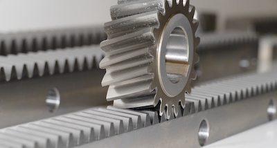
Figure 2: Rack and pinion gears
The rack is machined into the piston and the rack is precisely engaged to the pinion gear. When the chamber is filled with compressed air, the piston along with the rack extends or retracts which rotates the pinion gear via the geared connection.
Single rack vs dual rack design
Rack-and-pinion actuators offer the widest ranges of torque and rotation compared to other conversion mechanisms for converting linear force to rotational torque. It has a high mechanical efficiency and the torques that they are able to produce range from a couple of Nm to multiple thousands of Nm.
However, one potential drawback of the rack-and-pinion design is backlash. Backlash occurs when rack and pinion gears are not completely aligned and there is a small gap between each geared connection. This misalignment can cause wear on the gears during the life cycle of the actuator, which in turn increases backlash.
A double rack unit uses a pair of racks on opposite sides of the pinion. This helps eliminate backlash due to a counter force and also doubles the output torque of the unit and increases the mechanical efficiency of the system. In the double acting actuator shown in Figure 3, the two chambers on the sides are filled with pressurized air, which push the pistons to the center and to return the pistons to the initial position, the chamber in the center is in turn pressurized.
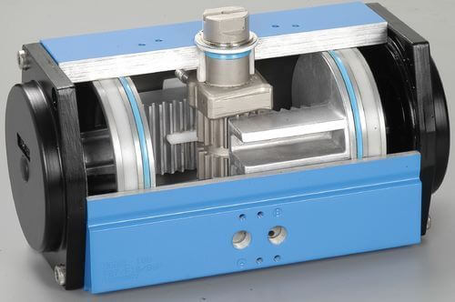
Figure 3: Double acting dual rack-and-pinion rotary actuators
Function
Rack-and-pinion pneumatic actuators can be either single-acting or double-acting. It is also possible for these actuators to provide multiple stops.
Single acting vs double acting
In a single-acting actuator, air is only supplied to one side of the piston and is responsible for the movement of the piston in only one direction. The movement of the piston in the opposite direction is performed by a mechanical spring. Single-acting actuators conserve compressed air, but perform work in only one direction. A downside of single-acting cylinders is the inconsistent output force through a full stroke due to the opposing spring force. Figure 4 shows a single-acting double-rack pneumatic rotary actuator.

Figure 4: Single-acting double-rack pneumatic rotary actuator
In a double-acting actuator, air is supplied to chambers on both sides of the piston(s). Higher air pressure on one side can drive the piston(s) to the other side. Double-acting actuators are used when work needs to be performed in both directions. Figure 5 shows a double-acting double-rack pneumatic rotary actuator.
One of the advantages of double-acting cylinders is the constant output force through a full rotation range. The drawbacks of double-acting cylinders are their need for compressed air for movement in both directions and a lack of a defined position in case of a power or pressure failure.

Figure 5: Double-acting double-rack pneumatic rotary actuator
Multiple positioning
Some rack-and-pinion actuators are able to stop at multiple positions through the range of a rotation by controlling the pressure at the ports. The stop positions can be in any sequence, making it possible for the actuator to selectively pass an inter-mediate stop position.
Travel stop bolts
Travel stop bolts are on the side of the actuator body (as seen in Figure 6) and allow for adjustment of the end positions of the pistons by limiting the rotation of the pinion gear from the inside. When installing the actuator, drive in both travel stop bolts until they contact the travel stop cap. Continue screwing the left travel stop bolt until the pinion slot visible on the top rotates to the position that is parallel to the length of the actuator body.
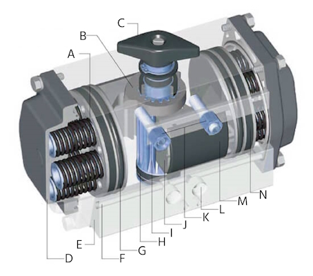
Figure 6: Rack-and-pinion pneumatic actuator components: spring cartridge pack (A), travel stop cam (B), position indicator (C), end cap (D), body (E), integral porting (F), piston seal (G), output shaft bearing (H), output shaft (I), piston (J), travel stop adjusting screws (K), pneumatic port (L), piston guide (M), and piston ring (N).
Standards
To be compatible and interchangeable with the products of various manufacturers, most pneumatic rack-and-pinion actuators have been standardized. These standards specify dimensions for various components such as actuator to valve interface, air ports, position indicator interface, and shaft driver shapes. They can be seen in Figure 6.
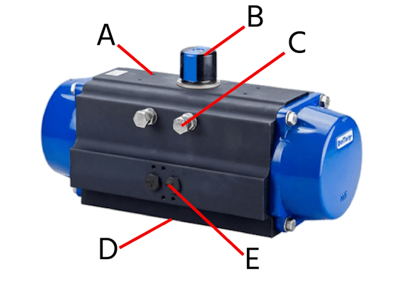
Figure 7: Housing and mounting surfaces: accessory interface per VDI/VDE 3845 (A & E), position indicator per NAMUR standard (B), travel stop bolts (C), ISO 5211 mounting (D).
ISO 5211: 2017
ISO 5211:2017 specifies requirements for the attachment of part-turn actuators to industrial valves, and can be seen in Figure 7. It specifies dimensions of the flange and driving components as well as torque values for the specified interfaces and couplings.
NAMUR VDI/VDE 3845: 2010-09
This standard contains specifications of the interface between the actuator and a process valve providing compressed air, and can be seen in Figure 7. It can also be used as an accessory interface on top of the actuator, for example, a position feedback switch or sensor. NAMUR-valves offer an assembly interface according to VDI/VDE 3845, which involves two air ports on the flat side of the valve as well as additional holes for fixing the valve onto the actuator body.
Selection criteria
There are various factors to consider when selecting a rack-and-pinion pneumatic actuator for your application.
For zero backlash at each end of the rotation and higher stop accuracy, a double rack actuator is recommended while for lighter duty applications where compact design is desired, a single rack actuator can be specified.
An actuator of a certain size will also likely provide a range of torque depending on the control pressure that is fed to it. Other criteria to consider when selecting a rotary actuator are range of oscillation, volume of air needed for the operation, control medium and Interface including output shaft options, flange sizes and pilot air ports.
Applications
Due to their constant torque output, rack-and pinion actuators are frequently used and often the preferred style of pneumatic actuators for valves. They are used for mixing, dumping, intermittent feeding, continuous rotation, turning over, positioning, oscillating, lifting, opening and closing and turning. These actuators are used for various mechanical functions in the steel industry, material handling, marine operations, construction equipment, mining machinery, and hydraulic power steering.


