


Voltage Transformers
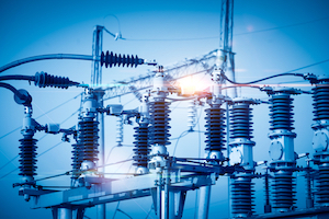
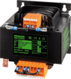
Figure 1: Voltage transformers
An electrical power system is a network that supplies, transfers, and consumes electric power. Power is generated at plants, transmitted through lines, and used in homes. Voltage levels must be measured to ensure optimal transfer, often requiring specialized transformers due to high voltages. Instrument transformers, such as voltage (or potential) transformers for high voltage and current transformers for high current, are used for these measurements. This article covers the construction, operation, measurement, types, and applications of voltage transformers.
Table of contents
- What is a voltage transformer
- Construction
- Working principle
- Measurement of voltage using a voltage transformer
- Types of voltage transformers
- Errors in voltage transformers
- Advantages and disadvantages
- Applications
- FAQs
View our online selection of transformers!
What is a voltage transformer
An electrical substation is a secondary station in the electricity generation, transmission, and distribution system where voltage is transformed from a high value to low or reverse using transformers. Electric power flows through several substations between power stations and the consumer, and the voltage may be changed in several steps.
The voltage generated in a power plant or substation is transmitted and fed to several industrial units and residential areas. It has to be ensured that the voltage generated is of optimum value, and also the voltage received after transmitting over several lines has not suffered major losses. Hence, it is essential to measure these voltages at various points.
The measurement of high-level voltages at power stations and load centers cannot be done by conventional voltmeters. A potential transformer is an instrument used for measuring high voltages in a transmission or distribution system. It is a step-down transformer that converts an input voltage to a lower output voltage which can then be measured by a voltmeter.
Note: The terms voltage transformer and potential transformer essentially mean the same, and both terms are used interchangeably throughout the article.
Construction
The construction of a voltage transformer is similar to that of a conventional power transformer with primary and secondary windings. The voltage produced at the load side is proportional to the number of turns in the secondary relative to the primary. The voltage transformation is given by:
V1 / V2 = N1 / N2
- V1: Voltage applied to the transformer primary winding
- V2: Voltage produced at the secondary (load) of the transformer
- N1: Number of turns in the primary
- N2: Number of turns in the secondary
For example, a transformer with N1=1, N2=10, having a primary winding voltage (V1) equal to 10, will have a secondary winding voltage equal to 1V.
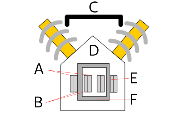
Figure 2: Potential transformer construction: high voltage winding (A), low voltage winding (B), high voltage bushings (C), oil-filled tank (D), insulation (E), and magnetic core (F)
A voltage transformer has a magnetic core (Figure 2 labeled F) similar to that of a conventional power transformer but with a large-sized core of silicon laminations. The magnetic core can be either shell-type or core-type.
The secondary side is wound adjacent to the core since it is easy to insulate a low voltage winding (Figure 2 labeled B). The primary, carrying high voltage (Figure 2 labeled A) is wound over the secondary winding with paper tape or cotton insulation (Figure 2 labeled E) in between.
The windings are immersed in an oil-filled tank (Figure 2 labeled D) providing better insulation in high rating voltage transformers (above 7kV). The high voltage terminals are brought out of the tank through oil-filled bushings (Figure 2 labeled C).
Working principle
A potential transformer is typically used to measure high voltages. The primary side of the potential transformer (Figure 3 labeled PT) is connected across the transmission line whose voltage (132 kV in Figure 3) is to be measured. The transmission line is connected to a load ‘A’ that receives electrical power from the line. The potential transformer is always connected in parallel across the line. The secondary side of the potential transformer is connected to a standard low-range voltmeter (Figure 3 labeled V). A current transformer is always connected in series with the line whose current is to be measured. Read our article to see a thorough comparison between voltage transformers and current transformers.
When voltage is applied to the primary winding, it induces a voltage on the secondary windings. This voltage is lower than the voltage on the primary winding and is proportional to the number of windings on the primary and secondary sides.
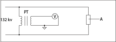
Figure 3: Working of a potential transformer
Measurement of voltage using a voltage transformer
- Connect the primary side of the voltage transformer to the high-voltage line that is to be measured.
- Connect a standard voltmeter (0-250V) across the secondary of the potential transformer.
- Note the voltage value across the transformer secondary displayed on the voltmeter.
If the ratio of the number of windings in primary to secondary is 1200:1, and the voltmeter measures 110V across the secondary,
- V2=110V
- N1=1200
- N2=1
- Therefore, V1=132 kV
Types of voltage transformers
Types of voltage transformers based on their construction
There are two main types of potential transformers based on their construction: wound-type and capacitor voltage type.
Wound-type potential transformer
The shell and core type potential transformers are classified as wound-type. The primary and secondary windings are wound on the core limbs with proper insulation. For measuring high voltages (typically greater than 10 kV), the construction becomes complex due to insulation problems. Hence, capacitive potential transformers are used to measure very high voltages.
Capacitive potential transformer
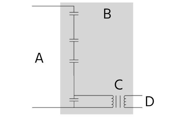
Figure 4: Connecting a capacitive potential transformer
A capacitive potential transformer uses a capacitive divider and an auxiliary transformer (Figure 4 labeled A). The capacitor divider eliminates the requirement of a high-rated potential transformer.
A capacitive-divider network (four capacitors in Figure 4) is connected across the high voltage to be measured (Figure 4 labeled B). When connected to an AC voltage, the capacitor starts charging to the magnitude of the voltage. The input voltage gets divided among the capacitors, thus reducing the high input voltage to a low value.
The low voltage obtained from the capacitive divider is stepped down (Figure 4 labeled D) using an auxiliary transformer. The shaded portion (Figure 4 labeled C) collectively describes a capacitive potential transformer that comprises a capacitor-divider and an auxiliary transformer.
Types of voltage transformers based on the operating voltage
Based on the system voltage used, voltage transformers are classified into
High-voltage voltage transformers
High-voltage potential transformers typically work on an input voltage greater than 69kV. These devices are suitable for measuring high voltages on distribution power lines. It is not economical to use a single transformer to measure voltages greater than 500kV (as the size of the transformer gets huge), and in this case, two transformer units are cascaded to produce the required voltage.
Cascading is the process of connecting two transformers in series. For example, to step down a high voltage of 100 kV to 10V requires a transformer with a turns ratio (number of turns in the secondary winding: number of turns in the primary winding) of 1:10000, making the transformer extremely bulky. Two transformers with a turns ratio of 1:100 can be used for the same purpose. The first transformer steps down the input voltage of 100 kV to 1 kV, which is fed to the primary winding of the second transformer. The second transformer steps down the 1kV input voltage to 10V at its output. Hence, transformers can be cascaded to get the exact voltage conversion of a single transformer, but with much lesser size and construction challenges.
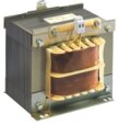
Medium-voltage voltage transformers
According to the IEEE standard, practical voltage levels (incoming voltage) in 5kV-35kV are often referred to as medium voltage. Some distribution lines may exceed 35kV, and these lines are categorized under high-voltage.
A medium-voltage distribution transformer provides the final voltage transformation in an electric power distribution system after stepping down the distribution line voltage to a level suitable for consumer use. These transformers are ideal for both indoor and outdoor applications depending on the level of input voltage range (see Table 1).
Note:The system voltage discussed in Table 1 for different voltage transformer types is for informational purposes only, and these values may vary according to the various standards used like IEEE, IEC, and ANSI.
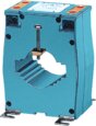
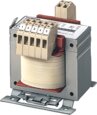
Low-voltage voltage transformers
A low-voltage transformer works on an input voltage of less than 600V. This transformer is used with measuring or monitoring equipment or as an auxiliary power source in the motor control panel.
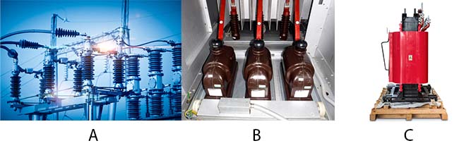
Figure 5: Types of voltage transformers, A: High-voltage voltage transformer, B: medium-voltage voltage transformer, and C: low-voltage voltage transformer
Table 1: Difference between low-voltage, medium-voltage, and high-voltage voltage transformers
| Transformer Type | Construction | Insulation type | System voltage | Indoor/outdoor applications |
| Low voltage | Single-phase, Three-phase | Resin cast, tape wound | 440V | Indoor |
| Medium voltage | Single pole three-phase, Double pole three-phase | Resin cast | 3.3 kV-33kV | Indoor and outdoor |
| Medium voltage | Single-phase earthed type | Oil-immersed | 3.3kV-33kV | Outdoor |
| High voltage | Single-phase earthed type | Oil-immersed | 66kV and above | Outdoor |
Types of voltage transformers based on function
Voltage transformers are classified into metering and protection types based on their function.
Metering type voltage transformers
Metering type voltage transformers are low rating transformers with high accuracy used for voltage measurement in metering devices.
Protection type voltage transformers
Protection type potential transformers are used for providing isolation and protection from high voltages during measurements. The windings of these transformers are electrically isolated and the low voltage side is not directly connected to the high voltage side.
Errors in voltage transformers
In a conventional transformer, the output voltage in the secondary winding is exactly proportional to the voltage on the secondary transformer. However, in voltage transformers, the voltage drops due to the reactance and resistance in primary and secondary windings. There are two types of errors namely phase-shift errors and voltage ratio errors present in the output voltage of a voltage transformer.
Phase shift error
The phase shift error is the difference between the phase of the primary voltage and the reversed secondary voltage. Ideally, the primary voltage remains in phase with the reversed secondary voltage. But practically, the reactance of the windings shifts the phase of the secondary voltage creating phase angle error.
Voltage ratio error
The voltage ratio error is the difference between the ideal voltage to be obtained and the actual voltage obtained at the secondary windings. Voltage ratio error percentage is given by:
{(V1 – Kn V2) / V1} ✕100
- V1: Primary voltage
- V2: Secondary voltage
- Kn: Nominal ratio (Rated ratio)
Advantages and disadvantages
Advantages
- Measures very high voltages on transmission lines safely.
- Enables an ordinary voltmeter to measure very high voltages.
- Provides protection by electrically isolating the voltmeter and high-voltage line.
Disadvantages
- A voltage transformer cannot measure DC voltage.
- Voltage transformers are expensive compared to conventional transformers.
Applications
Voltage transformers are commonly used in:
- Relay and metering circuits
- Electrical protection systems
- Measuring high-voltage transmission lines
- Synchronizing power generators and feeders( feeders are the power line through which electricity is transmitted in power systems)
FAQs
What is a voltage transformer used for?
A voltage transformer is used to measure high-voltage transmission lines and provide insulation in commercial metering systems.
What is the difference between a voltage transformer and a current transformer?
A voltage transformer measures a high voltage and is connected in parallel across the line. A current transformer measures a high current and it is connected in series with the line to be measured.
Why do potential transformers burst?
When a large current enters the transformer windings, the sudden surge may cause a transformer explosion. Transformers are programmed to turn off in case of a spike, but it can take up to 60 milliseconds for the shutdown.
How do I choose a potential transformer?
The main factors for selecting a potential transformer are service voltage, application (indoor or outdoor), place of installation, primary and secondary voltage ratings, and insulation level.


