


Does a Well Need a Foot Valve?
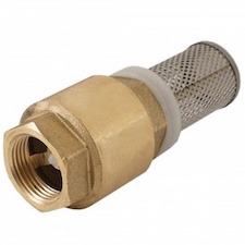
Figure 1: Brass foot valve
A well foot valve, installed at the end of a well's suction line, prevents water from flowing back into the well and keeps the pump primed. Without a foot valve, a non-primed pump can overheat or be damaged from running dry. A foot valve has a mesh to screen out contaminants from entering your system. This article discusses the operating principle, design, and installation of well foot valves.
Table of contents
- Well foot valve operating principle
- Well foot valve design
- Materials
- Well foot valve installation
- Well foot valve issues
- Well foot valve maintenance
- Well foot valve applications
- Well foot valve advantages
- FAQs
Well foot valve operating principle
A foot valve is a check valve with the addition of a strainer on its outlet port. The well pump turns on, creating a suction and pulling water from the well, through the valve, and towards the pump. When the pump turns off, the water in the suction line falls towards the well due to gravity. The pressure from the backflow closes the foot valve, stopping the column of water from reentering the well.
A well foot valve’s key feature is the strainer installed on its inlet port. This strainer prevents large debris from entering the valve and sticking it open or damaging it. Additionally, by blocking these debris, the strainer also protects downstream equipment.
Well foot valve design
Figure 2 demonstrates the typical design of a well foot valve. It does not include the strainer.
- Connection (A): Threaded connections are common. Flange connections are also available. See connection type section below.
- Body (B): The valve body protects the internal components.
- Flow control disc (C): The flow control disc opens and closes to control the flow rate through the valve.
- Spring (D): The spring provides tension so the valve opens at a specific cracking pressure. It also provides better sealing.
- Valve seat (E): The flow control disc closes against the valve seat to provide a tight seal.
Figure 2: Foot valve diagram (without strainer). Threaded connection (A), body (B), flow control disc (C), spring (D), and valve seat (E).
Strainer
A foot valve has a strainer, also called a filter or screen, installed on its inlet side. The strainer stops debris larger than the filter size from entering the valve and sticking it open. Additionally, it protects downstream equipment, such as the pump, from damage.
Filter size
Two filter sizes are available, 1 micrometer and 1.8 micrometers. For the vast majority of well foot valve applications, there is not a significant difference between these two sizes. Clay is the only particle consistently smaller than 2 micrometers. If there is a significant amount of clay suspended in the water, a 1 micrometer strainer will block much more of it than a 1.8 micrometer strainer.
Connection types
There are two common connection types used with foot valves: threaded and flanged.
-
Threaded: A significant difference between foot valves and check valves is that foot valves have threading only on the outlet side. The inlet side has a screen. There are three thread types. Learn more about each type by reading our thread design article.
- Female: Threaded on the inside to connect with piping that has threading on the outside.
- Flanged: Flanged connections are more suitable for industrial, high-pressure applications. They range in size from DN50 to DN100.
Materials
A foot valve remains submerged in water for the duration of its lifetime. Therefore, the material chosen needs to be rust and corrosion-resistant. Common materials for foot valves are stainless steel and brass.
-
Stainless steel
- 304 and 316 stainless steel foot valves are available.
- They work up to 150 °C (302 °F). They have an operating pressure up to 16 bar (232 psi).
- Suitable for sea water
-
Brass
- They work up to 60 °C (140 °F).
- Their operating pressure depends on their size. 1/2" to 1" (25 bar/362 psi). 1" to 2" (18 bar/261 psi)
- Not suitable for sea water
- More cost-effective than stainless steel
Well foot valve installation
Foot valves are appropriate for shallow and deep wells, whether using a one- or two-line jet pump (Figure 3). Also, submersible pumps use check valves. Read our well pump check valve article for more information on check valves in wells in general.
Before installing a well foot valve:
- Ensure that the foot valve is the correct size for flow conditions, not pipe size. Typically, foot valves work best at flow rates lower than 1.5 meters per second. Greater velocities can lead to cavitation of the foot valve and early failure.
- Take the entire system’s pressure into consideration, not just the pump’s pressure setting.
- Clean out built-up sediment. Shoot high-pressure water into the bottom of the well to push sediment up and out of the well. Wait for the water coming out of the well to be clear.
- Ensure the inside portion of the foot valve is clear of foreign objects such as metal chips, welding slag, and pipe scale. These can prohibit disc movement and damage the disc or seating.
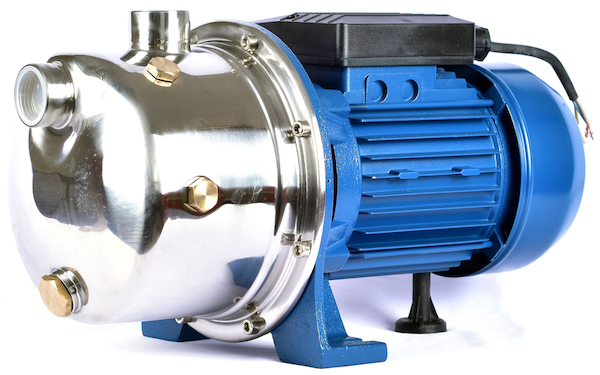
Figure 3: A jet pump.
During the installation of the well foot valve:
- Ensure the arrow on the valve faces towards water flow (up)
- Install the foot valve in a vertical position
- For shallow wells, the foot valve should be at most 7.6 vertical meters (25 vertical feet) below the pump’s inlet
- For deep wells that use a submersible pump, ensure to install check valves to alleviate stress on the foot valve. The first check valve should be approximately 6 meters (20 feet) from the pump. After that, install a check valve every 60 meters (200 feet) of piping.
- Ensure the screen is not at the bottom of the well but instead is 3 to 6 meters (10 to 20 feet) below the minimum pumping level (the level the water drops to while the pump is operating).
Well foot valve issues
Loss of water pressure from a pump does not necessarily mean an issue with the foot valve. It’s also possible that there is damage to the piping between the valve and the pump that is also letting air into the suction. However, since all components are underground, dealing with these issues will require pulling up the piping and foot valve.
Foot valves have three common issues: wire drawing, disc flutter, and sediment buildup in the screen. The first two issues require foot valve repair, but the third is fixable without pulling up the piping. Therefore, trying to solve the issue of sediment buildup may be the best first step to take.
Wire drawing
Wire drawing occurs when high-velocity water or sediment flows past a rubber valve seat. Over time, a groove carves into the seat. When the valve closes, the groove remains, and small flows escape the valve, causing pressure creep (increase in outlet pressure). Alleviate pressure creep by running a faucet connected to the well. However, more significant issues can occur in systems that do not often run.
To avoid wire drawing choose the smallest foot valve possible to handle the media flow through the system. Smaller valves open more widely, keeping the sediment away from the seat and reducing flow velocity through the valve.
Disc flutter
Disc flutter occurs when a foot valve is used at a small portion of its full capacity which causes excessive wear over time. This issue can also be mitigated by carefully selecting the smallest valve possible to handle the media flow.
Sediment buildup on screen
Sediment buildup on the screen can clog the strainer and greatly reduce flow through the check valve. Surging the well is a standard method to prevent excessive sediment buildup in the foot valve screen. Using a surge block or a bailer is a preemptive measure to take. Compressed air can be pumped into the well to raise the water level. When the water level reaches the top of the well casing, the air is turned off to allow the water level to drop quickly. This action may shake loose some sediment from the foot valve, but is not as reliable as using a surge block.
Well foot valve maintenance
After lifting a foot valve out of a well, take the opportunity to disassemble it and determine if anything inside the valve is repairable. However, before disassembling the valve, determine whether or not the manufacturer will void the valve’s warranty if it is taken apart.
Disassembling a foot valve is a simple process. First, remove the screen and seat, and then remove the disc. Once the disc is removed:
- Examine the inside of the valve for cleanliness.
- Remove scale buildup on the stem and stem guide using white vinegar.
- Ensure there is no elliptical wear on the stem or guides. If there is, replace either or both.
- Ensure the flow passage is free and clear.
FAQs
Do you need a foot valve for a well?
Foot valves may not be necessary for shallow wells (less than 4 meters), but their advantage is the pump will always be primed and protected from debris in the well.
How do you check if a foot valve is working?
If the well pump is not staying primed, there is likely an issue with the piping or the foot valve and both should be seen to.
What’s the difference between a foot valve and a check valve?
A check valve is threaded on both sides and a foot valve is threaded on one side, with a screen on the other.

