Flow Principles
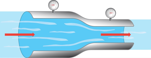
Figure 1: Flow properties change when flowing through a constriction
Fluid flow in a system has many properties that vary based on several factors. When designing a system and selecting valves, it's important to understand and consider these factors to select an optimal valve. This article overviews the different flow principles involved to help readers understand how to choose the best valve possible.
Flow factors to consider
- Pressure
- Pressure drop
- Pressure and velocity relationship
- Temperature and flow
- Flow coefficient
- Choked flow
- Flashing and cavitation
- Flow type
View our online selection of valves!
Pressure
Pressure is defined as the amount of force acting per unit area:
p=F/Awhere:
- p: pressure in Pascal (N/m2)
- F: force in Newton (N)
- A: surface (m2)
Pascal (Pa) is a relatively small unit. Therefore bar and psi are often used instead. 1 bar = 105 Pa.
When making pressure calculations in the process of determining the correct valve design to use in a system, understand the various aspects of pressure:
- Absolute vs relative pressure: Absolute pressure uses absolute zero as its reference point. Relative or gauge pressure uses atmospheric pressure as its reference point. When selecting a valve, using absolute pressure ensures the atmospheric pressure is considered when determining the total pressures placed upon the valve. Learn more about the types of pressure in our different pressure types article.
-
Static vs dynamic pressure: Static pressure is the pressure exerted by a liquid or gas at rest. Dynamic pressure is the pressure exerted by a fluid in motion.
- Static pressure: This pressure is resisted by the structural strength of the valve. Therefore, when designing a system, ensure the valves have enough strength and integrity to withstand the expected static pressure.
- Dynamic pressure: Dynamic pressure depends on the fluid's velocity and density. Designing systems to handle dynamic pressure is more complicated because considerations must be made about factors such as pipe diameter, flow rate, fluid viscosity, and the system's layout.
Static and dynamic pressure equations
The following are standard equations to help get an idea of a system's static and dynamic pressures. Actual valve and piping systems can be more complex due to fluid compressibility, frictional losses, changes in elevation, and flow acceleration.
The static pressure equation is:

Where:
- P: static pressure
- ⍴: fluid density
- g: acceleration due to gravity
- h: fluid column height above the point in question
The dynamic pressure equation is:

Where:
- q: dynamic pressure
- ⍴: fluid density
- v: fluid velocity
Pressure drop
When selecting a valve for a system, consider the pressure drop across the valve. The control valve pressure drop differs between the upstream and downstream pressures. Pressure drop impacts a system in the following ways:
- Efficiency: A high pressure drop across a valve can cause energy inefficiency, leading to higher operational costs.
- Flow rate: A high pressure drop can also lead to a low flow rate, disrupting the system's operation.
- Control: The pressure drop across a control valve controls the flow rate. The pressure control valve should be designed to provide the desired flow at the minimum pressure drop to save energy.
Read our pressure drop article to learn more about the factors that cause pressure drop.
Pressure and velocity relationship
Pressure and velocity have an inverse-proportional relationship. Therefore, adjusting the velocity of flow simultaneously adjusts the pressure. All valves offer some restriction to the flow, ranging from nearly insignificant (ball valve) to very significant (globe valve). This restriction is typically in the form of a reduced area for the flow, increasing its velocity and reducing its pressure.
The point of highest velocity, and therefore lowest pressure, is called the vena contracta (Figure 2).
The product of the velocity and area upstream of the constriction is equal to the product of velocity and area downstream of the constriction.
V1 * A1 = V2 * A2
Therefore, velocity and pressure can be adjusted by adjusting the size of the constriction. In control valves, this means moving the closing mechanism to a point between open and closed to modulate the flow rate.

Figure 2: The point where velocity is most constricted is the highest velocity and lowest pressure
Temperature and flow
Temperature can have a significant impact on flow through a valve. Therefore, consider the operating temperature range when designing a system and selecting a valve. Temperature can significantly affect the flow through a valve in the following ways:
- Material expansion/contraction: Valves have components made from different materials. Temperature changes can cause these materials to expand or contract. When high temperature causes a valve's parts to expand too much, leaks and reduced efficiency can occur.
- Viscosity changes: A fluid's viscosity is a measure of its resistance to flow. Viscosity is significantly influenced by temperature. As temperature increases, the viscosity typically decreases, making it flow more easily. In lower temperatures, the viscosity increases, potentially reducing the valve's ability to control the flow. Learn about valves designed for high viscosity by reading our valves for high viscosity fluid article.
- Pressure changes: Rising temperature can increase pressure in a valve, and falling temperature can decrease pressure.
- Seal performance: If the temperature is lower or higher than the valve seal's temperature rating, the seal can degrade or fail, leading to leaks.
Flow coefficient
The flow coefficient, either Cv or Kv, is a measure of the valve's capacity for fluid flow. Kv expresses the amount of water that can pass through a valve in cubic meters per hour with a pressure drop of one bar. Cv expresses the amount of water that can pass through the valve in gallons per minute with a pressure drop of one psi. A higher flow coefficient indicates a greater flow capacity, meaning more fluid can pass through the valve at a given pressure drop.
Additionally, a valve with a higher flow coefficient will have a lower pressure drop. The flow coefficient can be used to estimate the pressure drop across the valve.
| Flow coefficient | Equation to estimate pressure drop |
| Kv |  |
| Cv |  |
Where:
- ΔP: pressure drop across the valve (bar, psi)
- Q: Flow rate through the valve (m3/h, gpm)
- SG: specific gravity of the fluid
Learn more about the different flow coefficients and how to calculate each in our kv and cv calculator articles.
Choked flow
Choked flow means the pressure drop through the valve increases, but the flow rate does not because it has reached a maximum. This typically happens when the fluid's velocity has reached the speed of sound, also known as a critical flow condition. Choked flow is a major concern because it can lead to equipment damage and noises that are louder than recommended or required safety levels.
To avoid choked flow, consider the following when selecting a valve:
- Flow capacity: A too-small valve can quickly choke, limiting the flow rate regardless of pressure.
- Pressure drop: Because valve choked flow occurs when the downstream pressure drops to a certain level, ensure valves are rated for the maximum upstream and downstream pressures they will experience during operation.
- Fluid type: Gasses and liquids behave differently when flowing through a valve. Their specific properties, such as temperature, pressure, and specific heat ratio, influence the point at which choking occurs.
Flashing and cavitation
Choked flow is often a precursor to flashing and cavitation. These two phenomena occur when the pressure in the system drops below the liquid's vapor pressure, which causes bubbles to form in the liquid. When pressure rises again, the bubbles implode, creating shock waves that can damage valve components. Similar to choked flow, cavitation and flashing are damaging to equipment and dangerous to operators due to being very loud. Learn more about the specifics of the two by reading our cavitation and flashing article. Our article on cavitation in pumps, valves and pipes looks more closely at how it impacts valves.
Flow type
Different flow types can occur in a system. Some of these flow types can perform better in specific applications than others. Understanding this is important when selecting a valve to perform a specific function:
- Laminar: Laminar flow (Figure 3 left) is a fluid flow where fluid particles move in parallel layers with minimal mixing. Laminar flow is suitable for applications that require smooth flow, such as laboratory applications. Globe valves have excellent throttling and control capabilities, making them suitable for creating laminar flow conditions.
- Turbulent: Turbulent flow (Figure 3 right) is opposite of laminar flow. The fluid particles move chaotically with mixing and eddies. It typically occurs at high flow rates and with larger pipe diameters. Turbulent flow can be beneficial in mixing applications. butterfly valve work well in turbulent flow systems due to their robust design and ability to handle high flow rates.

Figure 3: Laminar flow (left) and turbulent flow (right)
- Transitional: Transitional flow occurs between laminar and turbulent flow. Operators should be aware of this flow type to understand that flow can switch back and forth between laminar and turbulent. Gate valves work well in these flow conditions because they can handle a wide range of flow conditions and open fully to allow high flow rates.
- Steady and unsteady: In steady flow, the fluid's velocity does not change over time, whether laminar or turbulent. In unsteady flow, the velocity varies at a given point in time. Steady flow requires a valve that offers a consistent flow rate, such as ball valves. Unsteady flow requires a valve that can react quickly to changes in the system, such as a solenoid valve.
- Compressible and incompressible: Compressible flow impacts gasses more than liquids, whereas incompressible flow is typically considered for liquids. Compressible flow needs a valve that can handle changes in density and volume, such as diaphragm valve. Incompressible flow needs a valve that can handle high pressures without leaking, such as gate valves.
FAQs
How are fluid pressure and velocity related?
Fluid pressure and velocity have an inverse proportional relationship. As one rises in the system, the other drops.
What is a flow coefficient?
A flow coefficient (Cv or Kv) measures the flow rate through a valve at a specific temperature at 1 bar or 1 psi.
How does temperature affect flow?
Temperature changes can change a fluid's viscosity and pressure. Also, temperature can negatively impact a valve's body and seal materials, degrading the flow conditions.


