


Cavitation In Pumps, Valves, and Pipes
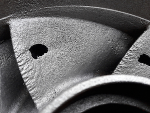
Figure 1: A cavitated pump impeller.
Uncontrolled cavitation in pumps, valves, and pipes causes damage. It significantly reduces the component's effectiveness and working life: cavitation damages a valve's seat, a pipe's wall, and a pump's impeller. One major issue with cavitation is that it can be prevented with proper system design.
Table of contents
What is cavitation?
Cavitation is a two-part process. First, pressure in a liquid system drops below the vapor pressure of the liquid at flowing temperature. This drop causes the liquid to phase into vapor bubbles. Second, the vapor bubbles encounter pressure above the liquid's vapor pressure, causing them to implode. This implosion creates a shock wave and micro-jets. If it occurs within one bubble diameter of a system component (e.g., valve seat, pipe wall, or pump impeller), it causes pitting damage. If left untreated, cavitation will severely damage these system components over time, reducing their effectiveness. Read our cavitation overview article for more information on cavitation and flashing.
Cavitation in pumps
Cavitation occurs in pumps for several reasons:
-
System design
- Reservoir above pump: If the reservoir is above the centerline of the pump, the pump creates a zone of low pressure at its inlet so the atmospheric head, or pressure head, can push liquid towards the inlet. Cavitation begins if the pressure at the inlet drops below the vapor pressure.
- Reservoir below the pump: A pump creates a suction head to pull liquid from the reservoir. The suction head is the vertical distance from the pump's centerline to the surface of the liquid in the reservoir. If the suction head is too large, the pump creates a vacuum effect, allowing cavitation.
- Vacuum cavitation: Other causes of vacuum conditions in a suction line are a dirty filter, clogged inlet, too long of a piping run, restricted or collapsed hoses, or too viscous fluid (e.g., cooled oil). In each case, not enough liquid enters the pump, allowing for more vapor to enter.
- Aeration: Aeration refers to air entering a system, whether purposefully or not. In pump systems, unwanted air can enter through holes or leaks, especially around unions and joints. Aeration may cause gaseous cavitation, which is typically underestimated because it does not cause the pitting damage that vaporous cavitation does. However, gaseous cavitation can significantly reduce the operating efficiency of hydraulic and lubricating systems.
How to avoid cavitation in pumps
The first step to avoiding cavitation in pumps is proper system design. This means ensuring that the inlet's Net Positive Suction Head (NPSH) is high enough. The NPSH measures how much higher the absolute pressure is than the flowing liquid's vapor pressure. Table 1 details the variables underlying NPSH. Combining the first three components, pressure head, atmospheric head, and velocity head, results in absolute pressure, or:
- P: Pressure
- Pa: Atmospheric pressure
- V: Liquid velocity
- ρ: Liquid density
- g: Gravitational acceleration
- Pv: Vapor pressure
The absolute pressure must be greater than the vapor pressure head to avoid cavitation, or:

Table 1: Variables necessary to calculate NPSH.
| Component | Description | Formula |
| Pressure head | The pressure at the pump inlet due to the height of the water column in the reservoir |  |
| Atmospheric head | The atmospheric pressure acting on the surface of the water column |  |
| Velocity head | The kinetic energy of the liquid flowing into the pump |  |
| Vapor pressure head | The vapor pressure of the liquid at flow temperature | |
A pump is likely experiencing cavitation if there is a sound like gravel or marbles flowing through the pump. Some suggestions for reducing cavitation are:
- Motor speed: Reducing the pump's motor speed slows down how fast liquid enters the pump, reducing the pressure drop at the inlet.
- Impeller inducer: Am impeller inducer operates directly upstream of the impeller. Its purpose is to raise the absolute pressure at the inlet, reducing the chance of cavitation.
- Liquid level at inlet: Increasing the liquid level at the inlet can reduce the possibility of a vacuum forming.
- Temperature: If possible, reduce the temperature of the system components around the pump or the liquid's temperature. As temperature increases, the vapor pressure increases exponentially.
Cavitation in valves
With some control valves, there is a significant pressure loss at the valve's inlet. Some notable exceptions are full-bore ball valves, gate valves, and cone valves, as long as users follow the recommendation of not using any of these valves to throttle flow. Flow-modulating valves, such as needle, globe, and butterfly valves, are significantly more susceptible to cavitation due to pressure losses at the inlet.
Note: Ball valves do modulate flow in everyday life. For example, these valves are common for outdoor hose faucets or kitchen sinks. However, when precision is necessary, ball valves are not optimal. Read our characterized ball valves article for more details.
Cavitation begins (i.e., bubbles form) at the valve inlet. Where cavitation ends (i.e., bubbles implode) depends on the valve's design. If pressure recovery within the valve occurs quickly, such as in a butterfly valve, then bubble implosion occurs, potentially damaging the valve plug or seat. Over time, cavitation damage will be severe enough to require valve replacement.
How to avoid cavitation in valves
As with pumps, proper system design can significantly reduce valve damage from cavitation; selecting the correct valve for an application is essential. The size of a valve, along with its flow coefficient (Cv), plays an important role. The Cv is the volume of water in gallons at 60 °F (16 °C) that flows each minute through a valve with a 1 psi (0.07 bar) pressure drop from inlet to outlet. The metric equivalent is the flow factor (Kv) with a discharge in cubic meters per hour. If the Cv is known, calculate the Kv with the following:

Valves with too small Cv for a system lead to higher pressure drops across the valve. If the pressure drops below the vapor pressure, the bubbles will implode when pressure recovers at the valve's outlet. If the Cv is too large for the system, the plug of a valve that throttles flow will sit very close to the valve seat. Liquid passing the plug will significantly reduce in pressure, potentially leading to cavitation within the valve.
In some cases, cavitation is unavoidable, for example, in high-temperature or viscosity liquid applications. However, there are still options to reduce the potential damage of cavitation.
- Valve location: If possible, install a valve in a relatively high-pressure zone, for example, at the lowest point in a piping system. The pressure drop at the valve may not be low enough to reach vapor pressure.
- Multiple valves: If the system requires a large pressure drop (e.g., heat exchanger), consider using multiple valves with moderate pressure differentials to achieve the result. The gradual pressure drop can limit cavitation intensity at any given point.
- Multi-stage trim: A multi-stage trim in a valve gradually reduces the pressure drop, which reduces the build-up of bubbles.
- Hardened trim: If cavitation is light (incipient), a harder trim material, such as stellite, can reduce damage to important valve components.
Cavitation in pipes
Understanding cavitation in pipes means understanding where and how pressure loss occurs. Pressure loss in a pipe is convenient to understand and calculate using the Hazen-Williams Equation:

- hf: head loss due to friction
- k: constant based on unit system (0.85 for metric, 1.32 for imperial)
- Q: Volumetric flow rate
- L: Length
- C: Pipe roughness coefficient (1 = smooth, <1 = rough)
- d: Pipe diameter
And Minor Loss formula:

- hf: minor head loss
- k: minor loss coefficient
- V: flow velocity
- g: acceleration due to gravity
And finally, the Total Energy Loss formula:

Important conclusions from the Hazen-Williams Equation are that pipe length, liquid flow rate, and pipe diameter play an important role in pressure loss in a pipe.
- Length: The longer the pipe is, the more pressure loss.
- Flow rate: The higher the flow rate, the more pressure loss.
- Pipe diameter: The wider the pipe diameter, the less pressure loss.
According to these conclusions, reducing pressure loss should be as simple as enlarging a pipe's diameter. However, experimental results show that increasing pipe diameter only reduces pressure loss at low flow rates. The reason for this is a minor loss variable that the Hazen-Williams Equation does not account for: turbulence.
When the liquid in a pipe encounters the pipe's walls or a turn (e.g., elbow joint), it creates turbulence. Turbulence throughout an entire system, especially smaller systems, adds to significant zones of pressure loss, increasing the possibility of cavitation.
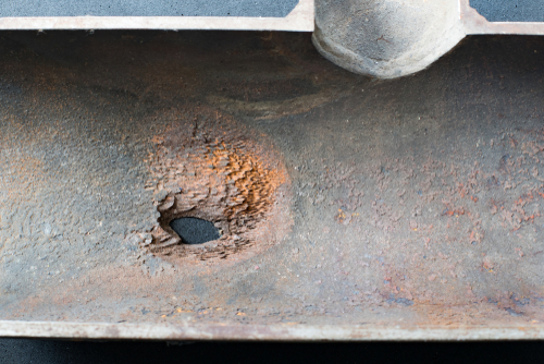
Figure 2: Cavitation damage on a pipe wall.
How to avoid cavitation in pipes
When designing a piping system, certain design choices can significantly reduce pressure loss and diminish the possibility of cavitation.
- Length: Investigate ways to reduce the length of piping sections where possible.
- Booster pump: Booster pumps increase pressure in a liquid. For relatively long sections of pipe (e.g., oil pipes), determine if one or more booster pumps are necessary to keep pressure above vapor pressure.
- Welding: If welding sections of pipe together, ensure that the weld surface inside the pipe is not too thick. This can create turbulence, which reduces pressure and may lead to cavitation.
- Pipe bending: A pipe bend results in less friction loss than the abrupt change in direction that elbow joints offer.
- Fittings: Every addition of a fitting (e.g., valves and joints) to a piping system provides a source of potential failure, which can allow air to enter the pipe and increase the possibility of cavitation.
FAQs
What causes cavitation in a valve?
A liquid's pressure greatly reduces at a valve's inlet. If the pressure reduces to the liquid's vapor pressure, bubbles form. Upon pressure recovery at the outlet, the bubbles implode and cause damage.
What causes cavitation in a pump?
If the absolute pressure at the pump's inlet is not high enough, pressure drop through the pump will go below the liquid's vapor pressure.
What causes cavitation in a pipe?
Pressure loss in a pipe due to improper sizing or turbulence can cause cavitation.
