Reducing Energy Consumption Of Solenoid Valves
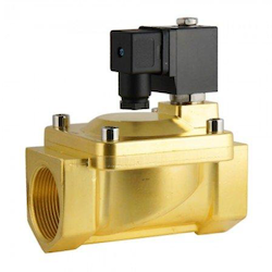
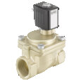
Figure 1: 2/2-way solenoid valve
Reducing the energy consumption of solenoid valves can result in measurable cost savings and enhanced system efficiency. Since solenoid valves are widely used to control fluid flow, even minor improvements in their energy use can result in significant overall savings. This involves choosing valves with lower power ratings, using advanced materials or designs, and minimizing energization time. This article discusses various techniques for optimizing solenoid valve design and operation, highlighting the importance of energy-efficient innovations.
Table of contents
- Selecting the correct valve size
- Design or type of solenoid valve
- Cycle patterns
- Solenoid valves with timers
View our online selection of solenoid valves and buy one today!
Selecting the correct valve size
Selecting the right size for the solenoid valve minimizes energy consumption. An oversized valve wastes energy in two ways:
- Excessive flow capacity: A valve with a flow rate exceeding process requirements allows more fluid through than necessary, wasting energy unnecessarily.
- Improper coil selection: Oversized valves often require larger coils to operate the valve. These larger coils consume more power, even when the valve is not actively controlling flow.
Always select a solenoid valve with the appropriate flow rate (Kv or Cv) and pair it with the correct coil size. This reduces the system's overall power consumption.
Design or type of solenoid valve
The energy consumption can vary significantly across different types of solenoid valves.
Normally open vs normally closed
A normally open (NO) solenoid valve remains open when de-energized, while a normally closed (NC) valve stays closed. When selecting between NO and NC configurations, safety should be the primary consideration, followed by energy efficiency.
If the valve’s default function is to block flow, an NC valve is preferred as it stays closed without consuming power. Using an NO valve in such cases leads to unnecessary energy usage, as it must remain energized to keep closed.
Read our normally open vs normally closed solenoid valve article for more details.
Direct vs indirect
Indirect-operated valves are more energy-efficient, as they utilize the medium's pressure to activate the valve. They are ideal for energy-sensitive applications, such as HVAC systems and automated irrigation. A direct-acting solenoid valve requires continuous electrical power to maintain its position.
Latching solenoid valves
Latching solenoid valves hold their open or closed position without continuous power. They are highly energy-efficient and ideal for battery-powered or mobile applications.
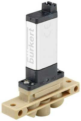
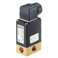
Figure 2: Latching solenoid valve
Kick and drop coils
Kick and drop coil initially applies a high voltage to quickly actuate the solenoid, then reduces the voltage to maintain its position. Solenoid valves, such as the Burkert 6014 and Burkert 6407, utilize kick and drop coils to minimize energy consumption. Kick and drop coils are more common in DC-powered solenoids. These solenoids maintain a constant current, which can lead to higher electricity consumption.
Cycle patterns
Cycle patterns describe how often and how long a valve remains in its open or closed state during operation. Solenoid valves operate with different cycle patterns, depending on the system's specific needs. Solenoid valves that operate frequently (with rapid open-close cycles) consume more energy than those with longer cycle durations.
To optimize performance and efficiency, monitor cycle patterns and energy use throughout the day. Key parameters to track include:
- The time taken by the valve to switch states
- The time spent in the open or closed position
- The energy consumption during each stage
Example
Compare two solenoid valves based on their cycle pattern and energy consumption for an automated irrigation system that operates once a day for 30 minutes.
Step 1: Cycle pattern
Assume both valves take the same time to open and close and operate once daily for 30 minutes.
Table 1: Cycle patterns of Valves A and B
| Cycle pattern overview | Time |
| Amount of time to open | 0.0033 hrs (20 seconds) |
| Amount of time to close | 0.0033 hrs (20 seconds) |
| Time in open position | 0.5 hrs (30 minutes) |
| Time in closed position | 23.4934 hrs (Remaining time in a day) |
Step 2: Energy consumption
Table 2: Energy consumption of Valves A and B
| Valve type | Energy to open (Wh) | Energy to close (Wh) | Energy in open position (Wh) | Energy in closed position (Wh) |
| Valve A | 0.05 | 0.05 | 0.1 | 0 |
| Valve B | 0.03 | 0.03 | 0.06 | 0 |
Calculate the energy for each operation phase to find the total daily energy consumption for each valve.
-
Valve A:
- Opening: 0.05 Wh
- Closing: 0.05 Wh
- Open position: 0.05 Wh (0.1 Wh/2 for half an hour of operation)
- Closed position: 0 Wh (not consuming energy)
- Total daily consumption: 0.15 Wh
-
Valve B:
- Opening: 0.03 Wh
- Closing: 0.03 Wh
- Open position: 0.03 Wh (0.06 Wh/2 for half an hour of operation)
- Closed position: 0 Wh (not consuming energy)
- Total daily consumption: 0.09 Wh
Conclusion
Based on the comparison, Valve B is more energy-efficient for this specific cycle pattern. However, cost, maintenance needs, and system complexity should also be considered to make a well-informed decision.
Note: The energy consumption values in the table represent typical usage for solenoid valves. It incorporates both the initial power required to open the valve and the holding power needed to keep it open. The values in the table are averaged to reflect overall daily energy consumption.
Solenoid valves with timers
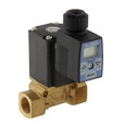
Solenoid valves with timers optimize energy use by activating the valve only during required periods, preventing unnecessary operation and energy waste.
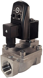
Figure 3: An analog timer installed on a solenoid valve
FAQs
What is a low power solenoid valve?
A low power solenoid valve operates with minimal energy, making it ideal for battery-powered or energy-sensitive applications.
How can I reduce solenoid valve current consumption?
Reduce current consumption by optimizing coil design, using PWM control, and selecting the right valve size.
Why is solenoid valve low power consumption important?
Low power consumption reduces energy costs, extends battery life in portable systems, and enhances overall system efficiency.


