


Solenoid Valve Timer - How it Works
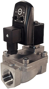
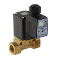
Figure 1: An analog timer installed on a solenoid valve
A solenoid valve timer automates the valve's opening and closing intervals. The integrated electronic timer circuit is a simple and cost-effective method of automating control over the flow of liquids or gasses. This article explores the features of solenoid valves with timers, their working, installation, and applications.
Table of contents
View our online selection of timers and solenoid valves!
Integrating a solenoid valve with a timer
Integrating a solenoid valve with a timer helps automate the valve's opening and closing intervals. The timer allows for the programming of specific intervals during which the valve will remain on or off. For instance, the timer can open a solenoid valve for ten seconds and then turn it off. This is ideal for remote locations with limited human access, like a condensate drain valve.
The main features of a solenoid valve with an automatic timer are:
- Precision control: The timer circuit allows for precise automated control of the valve's opening and closing, ensuring fluid flows exactly when and for how long it's needed.
- Flexibility: The timer circuit can be programmed for different timing intervals, making solenoid valves with timers adaptable to various applications. Also, the timers can be controlled in various ways, including manual or programmable logic controller (PLC).
Analog timer
SMD-720 is a commonly used analog timer for solenoid valves, providing a reliable solution for time delay solenoid valve applications. This timer has an on-off program that repeats infinitely and can be adjusted according to the user's requirements. The timer allows for adjustable ON and OFF intervals - an on time anywhere between 0 - 10 seconds and an interval (OFF) time between 0 and 45 minutes. The timer program can be interrupted by switching off the power supply.
Product description
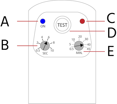
Figure 2: Analog timer's front panel: LED status in the ON position (A), ON time (B), LED status in the OFF position (C), knob (D), and OFF time (E).
- A: The LED lights up when the timer is on.
- B: Rotate the knob to set the valve's ON time in seconds. The solenoid valve remains on during this interval. For instance, rotating and setting the knob to 6 will send a pulse signal for 6 seconds into the solenoid valve.
- C: LED lights up when the timer is off. This helps to determine visually if the timer is on or off.
- D: The TEST button enables the retrieval of the latest used program stored in the timer's memory. This program is automatically loaded in its initial state when the power supply is restored or when the TEST button is activated. This function allows for easy access to previously used programs without manual reprogramming.
- E: Adjust the OFF time (in minutes) by rotating this knob. For instance, setting a value of 20 minutes will halt the operation of the solenoid valve by cutting off the electric signal sent to it for 20 minutes.
How to connect solenoid valve to timer
Electrical connections
To connect a solenoid valve to a timer, position the timer between the connector and solenoid valve, ensuring all components are clean, dry, and without any moisture. Place the rubber seals correctly to safeguard the construction against moisture damage. Secure the screw; ensure the torque applied is within 0.5 Nm and the rubber seals are tightened properly (Figure 3).
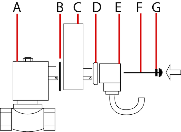
Figure 3: Components to install an analog timer: solenoid valve (A), rubber seal (B), timer (C), rubber seal (D), valve connector (E), screw (F), and rubber gasket (G).
Setting up program
The timer is loaded with a program that repeats cycles of turning ON and OFF (Figure 4). The ON period determines the time the solenoid valve remains open. The duration of the idle interval, during which the valve remains inactive, is determined by the OFF period. To restart the program, simply press the TEST button, deactivate the power supply, and reconnect it. The desired durations for the ON and OFF periods can be manually adjusted by rotating the knobs (Figure 2 labeled B and E).
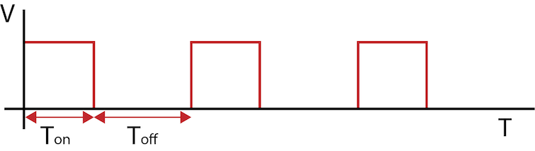
Figure 4: Waveform showing the ON and OFF periods of the solenoid valve
Digital timer
A digital timer like the AF-TD displays the solenoid valve’s ON and OFF periods using numbers on a digital display. The timer can be programmed to turn the solenoid valve on and off as needed (between 0 and 100 hours).
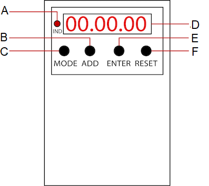
Figure 5: A digital timer's front panel: ON position LED (A), button to set the time duration (B), mode button (C), time display (D), ENTER button to confirm the settings (E), and button to restart the last mode saved (F).
Digital timer programming
The digital timer can be programmed using any of the following methods:
- Repeating ON-OFF cycle
- Repeating OFF-ON cycle
- ON-OFF period; single ON period and OFF afterward
Repeating ON-OFF cycle
A common practical application for a solenoid valve with an integrated digital timer and an infinite on-off cycle is an automated irrigation system for farms or gardens. By programming the digital timer, the watering schedule can be automatically adjusted, ensuring that plants receive the optimal amount of water without requiring any manual intervention. Perform the following steps to program the digital timer in this configuration:
- Press the MODE button on the timer panel to select 'ON-OFF.'
- To configure the duration for the ON period, press the ENTER button. The initial pair of digits represents the hours, the next pair represents the minutes, and the final pair represents the seconds. Utilize the ADD button to modify the currently flashing number, and press ENTER to proceed to the subsequent number. Repeat this procedure until the last number is set, at which point the first digit will begin flashing. Follow the same steps to establish the duration for the OFF period. For instance, consider an application where the solenoid valve remains on for 30 minutes and off for 40 minutes. Opt for the 'ON-OFF' mode and press the ENTER button. Use the ADD button to choose '0' for the initial digit and press ENTER to proceed to the subsequent number. Repeat this procedure until the final number is configured, making sure that the display exhibits 00:30:00. Follow these same steps to establish the duration for the off period, ensuring that the display reflects 00:40:00 upon completion.
- Once the OFF period's last digit is set and confirmed by pressing the ENTER key, the text 'ON-OFF' will flash for 3 seconds before the cycle initiates. Within this timeframe, the timer transmits the current to the valve actuator to commence operation, causing the indicator on the left side of the panel to illuminate. In the event of an immediate timer activation, press the RESET button while the text 'ON-OFF' is displayed for three seconds.
- In a temporary power interruption, the timer will experience the same effect as pressing the RESET button. Press the MODE button to halt the timer and keep it off, prompting the screen to exhibit the current mode, 'ON-OFF.' To choose an alternative mode, use the MODE button repeatedly.
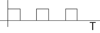
Figure 6: Waveform showing infinite ON-OFF cycle
OFF-ON cycle (repeating infinitely)
The terms 'OFF-ON' and 'ON-OFF' both describe the same functionality: a timer's ability to continuously cycle a device on and off without a predetermined end time. Essentially, the timer will keep the device cycling indefinitely until it is manually stopped or the power supply is disconnected. The only distinction between the two modes is the sequence in which 'ON' and 'OFF' occur. An infinite 'OFF-ON' cycle means the device will turn off first and then turn on, while an infinite 'ON-OFF' cycle means the device will turn on first and then turn off.
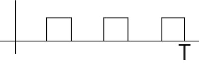
Figure 7: Waveform showing infinite OFF-ON periods
ON-OFF cycle (single ON period and OFF afterward)
In the ON-OFF cycle (single period ON and afterward OFF), the timer operates for some time and remains off thereafter (Figure 8). The cycle doesn't repeat infinitely as in the previous cases. One typical application in this mode is for controlling the flow of a liquid or gas in an industrial process. For example, in a water treatment plant, the solenoid valve with a digital timer could be used to control the flow of a chemical solution into a mixing tank at a set time interval. The digital timer could be set to allow the solenoid valve to be open for a specific amount of time, say 30 seconds, allowing the chemical to flow into the mixing tank. Once the 30 seconds are up, the timer would close the solenoid valve, stopping the flow of the chemical solution. This process would then repeat at regular intervals as determined by the timer, ensuring that the correct amount of chemical is added to the mixing tank consistently.
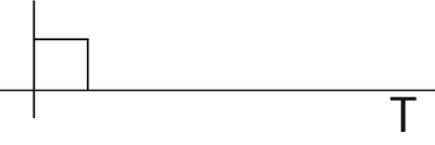
Figure 8: Waveform with ON-OFF cycle (single ON period and OFF afterward)
Precautions
- Ensure the timer-integrated solenoid valve is installed in a dry and well-ventilated environment. In the case of a moist environment, it is crucial to prevent any moisture from entering the coil or device. Take adequate precautions during installation to ensure safety and prevent the risk of electric shock, burns, or other injuries. Additionally, keep the device away from flammable materials.
- Install only when the system is completely disconnected from the electrical supply, cooled down, and depressurized.
- Always turn off the power supply before installing the timer to eliminate the possibility of electric shock and accidental device activation.
- After completing the installation, carry out commissioning procedures. This involves testing the valve's functionality, performance, and safety features, such as leakage rates, response times, and pressure ratings.
Read our articles on solenoid valve maintenance and installation for more details.
Applications
Timed solenoid valves are commonly used in industrial applications where precise control of fluid flow is essential. Here are a few examples:
- Air dryers: Solenoid valves with digital timers (infinite on-off) can be used in compressed air systems to control air flow and ensure the air dryer is functioning properly. The valve can be set to open and close at specific intervals, allowing air to flow through the dryer and be dried before it reaches downstream equipment.
- Shower timers: Solenoid valves with timers can be used in shower systems to limit the time a shower can take. The valve can be set to open and allow water to flow for a while before automatically shutting off. A digital timer with a single on-off cycle would be suitable for this application. The solenoid valve needs to be turned on for a specific amount of time and then shut off automatically to limit the amount of time the shower can take.
- Condensate drains: Solenoid valves with digital timers (infinite on-off) can be used in air compressor systems to drain the condensate that collects at the bottom of the tank. The valve can be set to open and close at specific intervals, allowing the condensate to be drained without disrupting the compressed air system, and this process continues indefinitely.
- Lubrication systems: Solenoid valves with timers can be used in automated lubrication systems to control lubricant flow to various parts of a machine. Using a digital timer with a single on-off cycle would allow the solenoid valve to be turned on for a predetermined amount of time, say 5 or 10 seconds, and then shut off automatically.
FAQs
What is a battery-operated solenoid valve with a timer?
A battery-operated solenoid valve with a timer is powered by a battery and includes a built-in timer mechanism.
How to connect a solenoid valve to a timer switch?
Install the timer between the solenoid valve and the connector. The installation process depends on the manufacturer; hence, referring to the manual for the connection process is necessary.


