How to Wire a Pneumatic Solenoid Valve

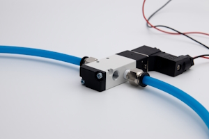
Figure 1: A pneumatic solenoid valve cannot function without proper wiring to a power source.
Wiring a pneumatic solenoid valve allows for precise control over the flow and direction of air within a pneumatic system, ensuring reliable and efficient operation tailored to specific needs and applications. This guide explains how to incorporate various components, such as switches, timers, relays, and programmable logic controllers (PLCs), to enhance control over the pneumatic solenoid valve's operation. By following these detailed instructions, one can achieve precise and automated management of a pneumatic system.
Several different device types are mentioned throughout this article. It's important to always consider the voltage requirements of any device that needs to be wired to another. If all devices in the circuit have the same voltage requirements, they can be directly wired to the power source. However, additional steps must be taken if the devices have different voltage requirements. A voltage regulator or step-down transformer should be used for devices needing a lower voltage. Conversely, a step-up transformer or DC-DC converter is necessary for devices requiring a higher voltage. A power supply with multiple outputs or separate power supplies should be considered in circuits with multiple voltage levels. Additionally, relays can be used to electrically isolate devices with different voltage requirements, ensuring the safe and effective operation of the circuit.
Note: The advice throughout this article primarily focuses on DC solenoids, meaning the solenoid has a positive and negative terminal. AC solenoids are not polarized and therefore live and neutral wires can connect to either of the terminals.
Table of contents
- How to wire a pneumatic solenoid valve to a power source
- Switches
- Timers
- Relays
- Programmable logic controllers (PLCs)
- Pressure and flow sensors
View our online selection of pneumatic solenoid valves!
How to wire a pneumatic solenoid valve to a power source
The following step-by-step instructions explain how to connect a pneumatic solenoid valve to a power supply. Further sections explain how to add other components to the circuit to gain more control over the solenoid valve's operation.
- Gather necessary tools and materials: Solenoid valve, power supply, wires, connectors, screwdriver, and wire stripper.
- Identify the solenoid valve terminals: There are two terminals: A DC solenoid has one for the positive connection and one for the negative connection. AC solenoids are not polarized so either terminal can connect to the live or neutral wire from the power source.
- Prepare wires: Prepare the wires by stripping about 6 mm (1/4 inch) of insulation from the ends using a wire stripper.
- Connect the wires to the solenoid valve: Attach the stripped end of the positive wire to the positive terminal of the solenoid valve and secure it using a connector or by tightening the terminal screw. Repeat this process for the negative wire and terminal.
- Connect the wires to the power supply: Attach the other end of the positive wire to the positive terminal of the power supply. Similarly, connect the negative wire to the negative terminal of the power supply.
- Secure connections: Secure all connections to ensure they are tight and prevent any loose connections that could cause malfunction.
- Test: Test the system by turning on the power supply and activating the solenoid valve to ensure it operates correctly. Listen for a clicking sound, which indicates the valve is functioning.
Switches

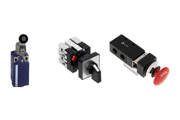
Figure 2: Examples of switches that can control a pneumatic solenoid valve from left to right: limit switch, rotary controls witch, emergency stop button switch
Switches provide a reliable and user-friendly means of controlling pneumatic solenoid valves, offering both manual and automated options for diverse operational needs. The switches do not need to be mounted directly to the pneumatic solenoid valve. They are more likely to be located in a control center or a convenient location for the operator. This setup allows for easier access and control, whether it's for manual operation, automated control, or emergency stops. The wiring connects the switches to the solenoid valve, enabling remote operation.
-
Limit switches
- Wiring: Connect one terminal of the limit switch to the positive terminal of the power supply. Connect the other limit switch terminal to the solenoid valve's positive terminal. The negative terminal of the solenoid valve should be connected to the negative terminal of the power supply.
- Operation: The limit switch will automatically control the solenoid valve based on the position of other mechanical components. Learn more in our comprehensive limit switch guide.
-
Manual rotary switches
- Wiring: In a typical rotary switch, connect terminals 1 and 3 (input terminals) to the power supply and terminals 2 and 4 (output terminals) to the solenoid valve.
- Operation: Turning the rotary switch from 0 to 1 will complete the circuit and energize the solenoid valve.
-
Emergency stop buttons
- Wiring: Connect one terminal of the emergency stop button to the positive terminal of the power supply. Connect the other terminal of the emergency stop button to the positive terminal of the solenoid valve. The negative terminal of the solenoid valve should be connected to the negative terminal of the power supply.
- Operation: Pressing the emergency stop button will open the circuit and de-energize the solenoid valve.
Timers
Wiring a timer to a pneumatic solenoid valve allows for automated scheduling, ensuring the valve operates only when needed, which reduces wear and energy usage. This setup enhances process consistency by providing accurate and repeatable timing for valve activation and deactivation, minimizing the need for manual adjustments.
- Wiring: As seen in Figure 3, connect the timer's terminal 1 to the solenoid valve's positive terminal through the connector. For AC solenoid valves, connect terminal 1 to the phase wire. Connect terminal 2 to the negative pole (DC) or the neutral wire (AC). Always connect the ground.
- Operation: Set the timer to control when and for how long the solenoid valve is energized. Learn more in our article about solenoid valve timers.

Figure 3: A wiring diagram for a solenoid valve timer connecting to a solenoid connector.
Relays
Wiring a relay to a pneumatic solenoid valve enables the control of high-power circuits with low-power signals, enhancing system safety and reliability. This configuration allows for remote operation and integration with various control systems, providing flexibility and improved automation in complex processes.
- Wiring: Connect the coil terminals of the relay to the control circuit (e.g., a switch or a PLC output). Connect the common terminal (COM) of the relay to the positive terminal of the power supply. Connect the normally open (NO) terminal of the relay to the positive terminal of the solenoid valve. The negative terminal of the solenoid valve should be connected to the negative terminal of the power supply.
- Operation: When the relay coil is energized, it closes the NO contact, completing the circuit and energizing the solenoid valve.
Programmable logic controllers (PLCs)

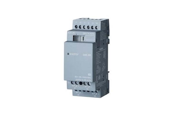
Figure 4: A digital PLC that can control a pneumatic solenoid valve based on inputs from other devices (e.g., pressure sensors)
Wiring a PLC to a pneumatic solenoid valve allows for precise and automated control of the valve's position, thereby regulating the flow and direction of air to and from a pneumatic cylinder and other pneumatic devices. This section covers how to connect a MVSC1-180 3/2-way directional control valve and a Siemens PLC. The process of wiring these two devices follows a typical methodology, however be sure to carefully examine manufacturer documents before trying with different valves and PLCs.
- Power supply: Use a 24V power supply for the pneumatic solenoid valve and the PLC.
- Connect the power supply
- Connect the positive terminal of the power supply to the common terminal (COM) of the PLC's relay outputs.
- Connect the negative terminal of the power supply to the negative terminal of the solenoid valve.
- Connect PLC to solenoid valve
- Connect one of the relay output terminals (e.g., DO1) of the PLC to the positive terminal of the pneumatic solenoid valve.
Pressure and flow sensors
To integrate pressure sensors and flow sensors into a control system, connect the output of the pressure sensor or flow sensor to an input terminal of a control device, such as a PLC or relay. Then, wire the control device's output to the solenoid valve according to the instructions provided in the PLC or relay sections. In operation, the pressure sensor or flow sensor will send a signal to the control device, which will subsequently control the solenoid valve based on the pressure or flow readings, ensuring precise and automated regulation of the system.
FAQs
How to wire a pneumatic solenoid valve?
Wiring a pneumatic solenoid valve involves connecting the valve's electrical terminals to a power source and control device, ensuring proper voltage and polarity.
What components are needed to wire a pneumatic solenoid valve?
To wire a pneumatic solenoid valve, you need the valve, a power source, control devices like switches or PLCs, and appropriate wiring tools.
How do you ensure proper voltage when wiring a pneumatic solenoid valve?
Verify the solenoid valve's voltage rating and match it with the power source to ensure proper voltage and avoid damage.
Can a pneumatic solenoid valve be controlled by a PLC?
Yes, a pneumatic solenoid valve can be controlled by a PLC by wiring the valve to the PLC's output terminals and programming the desired control logic.


