


How Does an Angle Seat Valve Work
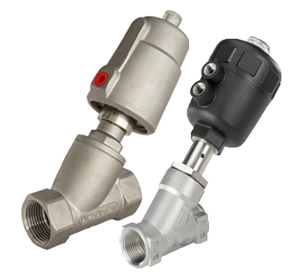
Figure 1: Pneumatic angle seat valves
An angle seat valve's primary feature is its angled seat design, which minimizes flow disruption and pressure loss. Additionally, this valve type is durable and has a high cycle life. It excels in harsh environments and handles high temperatures and viscosities.
Table of contents
- Angle seat valves vs other types of valves
- Angle seat valve design
- Pneumatic, electric, and manual angle seat valve comparison
- Applications
- Selection criteria
- FAQs
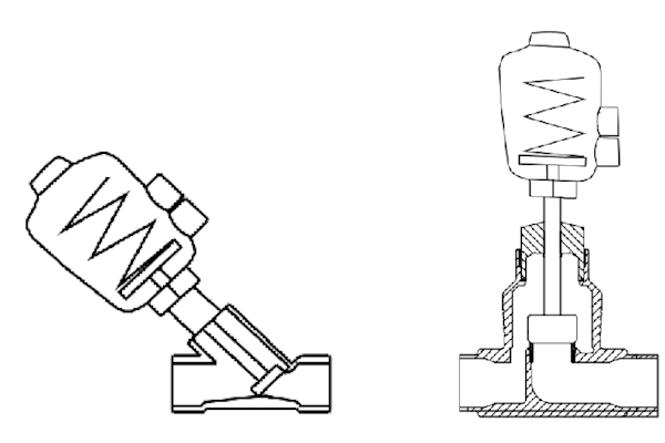
Figure 2: An angle seat valve or Y-Type globe valve (left) and a globe valve or Z-Type globe valve (right).
Manual angle seat valve
A manual angle seat valve is controlled by turning its handwheel (Figure 3 labeled A). This is a multi-turn valve, meaning the handwheel must be turned 360° or more to open or close the valve fully. A manual angle seat valve does not have a spring-return because the handwheel controls all movement.
Pneumatic angle seat valve
Actuators for pneumatic angle seat valves have a spring (Figure 4 labeled A) and a piston (Figure 4 labeled B). Air enters through the air port (Figure 4 labeled C) and pushes the piston up or down, depending on whether the valve is normally open or normally closed.
Piston movement will lift the disc from the valve seat or push the disc towards the valve seat. When air pressure is cut off, the spring returns the piston and the disc to their default positions.
3/2 way pneumatic solenoid valves are commonly used to control the flow of air to and from a spring-loaded pneumatic actuator. 5/2 way pneumatic solenoid valves can control air flow to and from double acting pneumatic actuators.
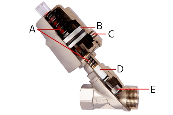
Figure 4: Section view of a pneumatic angle seat valve: spring return (A), piston (B), air port (C), packing (D), and plug/disc (E).
Electric angle seat valves
An electric actuator for an angle seat valve enables integration into broader process control systems. This capability provides precise positional control, allowing for fine-tuned flow regulation. An integrated position sensor ensures high accuracy and repeatability by providing continuous feedback on the valve's exact location. The system also accommodates optional external sensors to measure parameters such as temperature or pressure, providing valuable data for automated adjustments and proactive system responses.
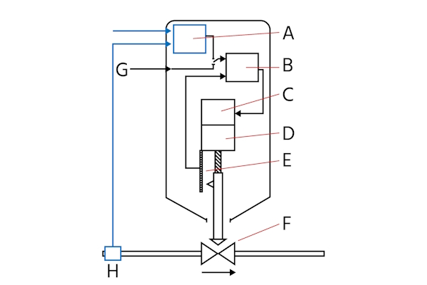
Figure 5: Angle seat valve's electric actuator function diagram. Blue elements are optional. Process control (A), position control (B), motor (C), gear (D), position sensor (E), angle seat valve (F), actual position (G), and external sensor (H).
Pneumatic, electric, and manual angle seat valve comparison
| Factor | Pneumatic | Electric | Manual |
| Power source availability | Ideal to use when there is reliable compressed air supply. Preferred in explosive environments due to no ignition risk | Best choice if electricity is readily available and precise control is needed. Suitable where compressed air is impractical. | Optimal where neither electricity nor compressed air is available. Ideal for direct control without automation |
| Control and automation needs | Suitable for automated processes requiring remote control | Offers finer control over valve positioning, ideal for integration into automated control systems | Best for applications where manual control is sufficient, especially for simple on/off operations |
| Environmental Conditions | Performs well in harsh conditions (wet, dusty, explosive) due to lack of electrical components | Suitable for clean environments. Consider IP rating for dust and water protection in challenging conditions | Good for a wide range of environments. Less affected by conditions due to non reliance on power sources or control systems |
| Response time and precision | Rapid response times, suitable for quick actuation needs. | Provides precise control, ideal for careful regulation of flow rate or pressure. | Depends on the operator. Suitable where valve actuation timing is not critical. |
| Cost | May require additional infrastructure for compressed air, but generally less expensive than electric valves | More expensive upfront due to precision control mechanisms but can save on operating costs where compressed air is not available | Most cost-effective in terms of initial investment and maintenance |
| Maintenance and lifespan | Requires regular maintenance of the air supply system to prevent contamination. | Requires less maintenance than pneumatic systems | Requires the least maintenance; however, operator accessibility must be ensured |
Applications
Angle seat valves are valued not just for their versatility, but for the specific advantages their angled design provides in demanding applications. Compared to other valve types, they excel in situations where durability, resistance to clogging, and efficient flow control are critical.
Food and beverage production
- Steam sterilization: Unlike standard globe valves, angle seat valves can handle high-pressure steam with minimal wear, ensuring reliable sterilization of equipment.
- Filling operations: Their angled seat allows for rapid opening and closing, making them ideal in bottling and canning lines where speed and accuracy are essential.
Chemical processing
- Chemical dosing: The robust design of angle seat valves ensures precise flow control, even with corrosive or aggressive media that might damage softer-seated alternatives.
- Harsh environments: Their stainless-steel construction and angled seat reduce turbulence and wear, extending service life in chemical plants.
Water and wastewater treatment
- Sludge control: The angled seat minimizes clogging and buildup, making these valves well-suited for slurry and sludge applications where other designs would quickly foul.
- Process reliability: In filtration and dosing systems, the quick response and resistance to contamination improve overall treatment efficiency.
Pharmaceutical manufacturing
- Clean steam systems: The angled seat design ensures tight shut-off and reliable performance at elevated temperatures, which is critical for sterile conditions.
- Fluid and gas control: Their precision and cleanability make them a better fit than ball valves in processes where product integrity is paramount.
Automation and HVAC
- High-cycle performance: In automated production lines, angle seat valves are preferred for their ability to handle millions of cycles without significant wear.
- Steam heating: Their tolerance for high temperature and pressure makes them more reliable than many alternatives in HVAC steam distribution systems.
Selection criteria
- Actuation
- Manual: Least expensive option
- Pneumatic: More expensive than manual but significantly less expensive than electric (not considering the source of compressed air). More likely to be approved for explosive environments because there are no sparking components.
- Electric: The most expensive option but also the most precise position control. Optional components allow for more complex integration into a system.
- Connection size: The valve's connection size should match the size of the system when possible. Double nipple fittings with different sized threads are available if necessary. For example, this fitting can have a 1 inch connection on one side and a 1/2 inch connection on the other side.
- Connection type: Connection types range from threaded (e.g., NPT, BSPP, metric) to welded and clamped connections. Valves with threaded connections are easier to install and remove from the system but welded connections are more leakproof.
- Body material: Brass and stainless steel are common body materials for angle seat valves. Brass is less expensive than stainless steel but also less durable. Additionally, stainless steel is necessary for sanitary applications.
-
Seal material: The seal material controls the valve's extremes because the seal will be damaged by extreme conditions sooner than the valve's body. Common seal materials are Teflon, EPDM, FKM, and NBR. Read our chemical resistance article to learn what seal materials work with your application.
- Choose EPDM for drinking water applications because this material does not affect the water's taste.
- Function
- Pneumatic: Pneumatic actuators can be normally open or normally closed with spring-return to default position. These actuators can also be double acting, meaning they don't have a spring and compressed air controls the position in both directions. Double-acting actuators offer more precision options than single-acting actuators.
- Electric: Electric actuators can also be normally open or normally closed. They have internal energy storage so in case of power loss they can return to their default position. Some electric actuators do not have this storage and therefore their position remains the same upon power loss.
- Max pressure difference at 20 °C/68 °F: The valve's seal material impacts the max pressure difference. For example, Teflon and PEEK seals are suitable up to 25 bar (362 psi), whereas NBR, EPDM, and FKM are suitable up to 16 bar (232 psi).
- Max temperature: The seal material also controls the max temperature. Teflon and PEEK are suitable for higher temperatures than NBR, EPDM, and FKM.
- Kv: Kv is a measure of the flow rate of water in m3/h at a pressure drop of 1 bar. Use the Kv calculator to calculate the required Kv for your application. Imperial units: Cv=1.16xKv.
-
Approval: Approvals indicate what environments an angle seat valve is suitable for. Common approvals include:
- Food grade: The valve is safe for use in food and beverage processing environments.
- Atex zone: The valve is safe for use in potentially explosive atmospheres within the European Union. Read our ATEX FAQ to learn more.
- IECEx: Provides international certification for equipment used in explosive atmospheres, ensuring compliance with global safety standards.
- DVGW: Certifies the valve for use in gas and water applications in Germany, ensuring it meets national safety and quality standards.
- UL certification: Indicates the valve has been tested and meets safety standards set by Underwriters Laboratories, commonly recognized in North America. Read our guide on UL certification for electronic products to learn more.
- Closes against flow: An angle seat valve can close in the opposite direction of the flow or it can close in the same direction. Choose a valve that closes in the opposite direction in applications where water hammer is a concern.
FAQs
What is an angle seat valve?
An angle seat valve uses a 45° seat to create a larger flow path, reducing pressure loss and wear, ideal for steam, high-temp, and viscous media.
How does a pneumatic angle seat valve operate?
A pneumatic angle seat valve operates by using air pressure to move a piston, which in turn opens or closes the valve for flow control.
What are the advantages of using an angle seat valve?
Angle seat valves offer high durability, superior flow rates, and are suitable for harsh environments, making them more efficient than ball or solenoid valves.


