Proportional Solenoid Valve Controller - How They Work
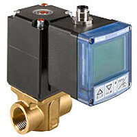

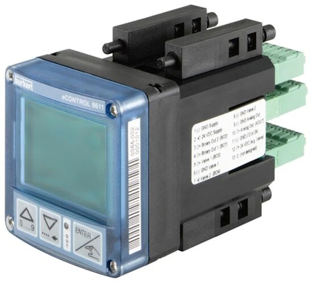
Figure 1: Burkert proportional valve controller 8611 (left) and 8605 (right)
A proportional solenoid valve controller regulates the electrical input to a proportional solenoid valve, ensuring precise, stable, and variable control over flowrate. The regulation of flowrate is most commonly used to control pressure, level, and/or temperature. The plunger position of a proportional solenoid valve can be controlled across a range of stroke positions by varying the power supplied to the solenoid coil. Proportional solenoid valves are often used in areas where precise fluid flow and pressure control is needed.
Buy Burkert Proportional Solenoid Valves and Controllers!
Table of contents
- Burkert proportional solenoid valve controllers
- Overview of 8611 vs 8605
- What is PWM?
- Advantages of Burkert PWM controllers
- PI (proportional and integral) control theory
Burkert proportional solenoid valve controllers
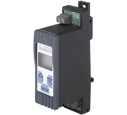
The Burkert 8611 and 8605 controllers control Burkert proportional solenoid valves, but can also control other brands' PWM valves. The 8605 is a dedicated proportional valve controller. The 8611 is a universal controller, capable of controlling PWM solenoid valves and other process valves and devices. Each controller is equipped with configurable control functions to ensure accurate and reliable process control. Additionally, multiple design options are available to meet the needs of process control applications.
Overview of 8611 vs 8605
Table 1: Overview of the differences between the Burkert 8611 and 8605 proportional solenoid valve controllers
 |
 |
||
| Type | 8605 | 8611 | |
| Function | Digital PWM control | Digital PI controller, Continuous 2-point, 3-point and On/Off control | |
| Versions | Rail or valve mounting | Fitting, wall, rail, cabinet, or valve mounting | |
| Signals |
- Set point (0-5 V, 0-10 V, 0-20 mA, 4-20 mA) - PWM output (80 Hz-6 kHz) |
- Set point (0-10 V or 4-20 mA) - Actual process value (4-20 mA) - Sensor input (0-10 V, 4-20 mA, Pt 100 or frequency) e.g., pressure, temperature, or flow - Control output signal (4-20 mA or PWM) - Binary input - Binary output - Outputs (continuous, discontinuous signal) |
|
| Operating voltage | 12, 24 VDC | 24 VDC | |
| Max. power consumption | 1 W (without valve) | 2 W (without valve) | |
| Valve outlet | Max. 2 A (PWM) | Max. 1 A (PWM) | |
| Software functions |
- Valve setting (frequency, min./max. opening) - Zero point cut-off - Temperature compensation - Ramp function - Down-/upload of parameterization |
- Controller setting - Valve setting (all Burkert proportional solenoid valves stored) - Sensor setting (all Burkert flow sensors stored) - Configuration of switching (binary) signals - Scaling of set point and process value signals - Valve and sensor setting - Code protection |
|
What is PWM?
Burkert’s 8611 and 8605 generate pulse width modulation (PWM) signals to control proportional solenoid valves. The PWM signal is a pseudo-analog signal manufactured from a digital signal that is switched ON and OFF.
The switching frequency and duty cycle define PWM characteristics.
-
Switching frequency:The switching frequency determines how fast a cycle between ON and OFF is completed.
- A switching frequency of 20 Hz would be 20 cycles per second.
-
Duty cycle: The duty cycle represents the percentage of the amount of time the signal is ON over the full cycle.
- A 75% duty cycle means the signal output will be ON 75% of the cycle.
PWM output
Although the PWM voltage pulses to the coil are square, the current delivered to the coil takes on a sawtooth waveform due to the coil's inductance and the duty cycle (Figure 2). This transformation occurs because the voltage across an inductor is given by the formula
where (L) is the inductance and di/dt is the rate of change of current. As the square wave voltage is applied, the current ramps up and down in a linear fashion, creating a sawtooth pattern. The result is a steady oscillation of the plunger in a balanced state, commonly referred to as dither. Dither reduces static friction and decreases hysteresis, where the actual plunger position lags behind the command position. In Figure 2, the time off (toff) and time on (ton) are determined by the duty cycle, and the nominal voltage (U) is what is supplied, creating the resulting current (I) waveform.
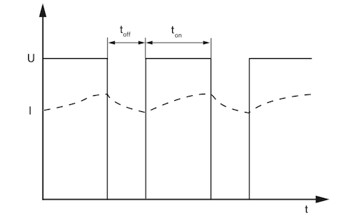
Figure 2: PWM signal: nominal voltage (U) and resulting current (I). toff and ton represent off and on times of the waveform.
PWM response optimization
Valve sensitivity and dither movement are influenced by coil properties, switching frequency, and duty cycle. A proportional solenoid valve's reaction to a PWM signal is most sensitive when operated in a specific switching frequency range (f) at an optimal duty cycle.
The point at which the valve is most responsive is known as the working point. An example of a working point is shown in Figure 3 at the intersection of the upper frequency and 60% duty cycle. At its upper (fHI) and lower (fLO) frequency limits the valve will react more slowly to a PWM signal. An example of the ideal operating range of a proportional valve is shown in Figure 3.
The limit frequencies, optimal duty cycle, and coil properties are all unique and crucial for accurate control of any valve. Malfunction of the valve or higher audible noise may result if a valve is controlled with incorrect operating parameters.
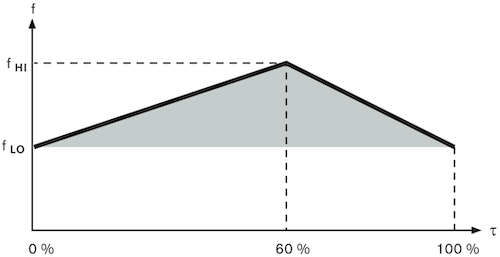
Figure 3: Proportional valve operating parameters. The x-axis is the duty cycle and the y-axis is the switching frequency range.
Advantages of Burkert PWM controllers
The benefit of using the Burkert proportional valve series with their solenoid controller, is that the correct switching frequencies and operating points are known for all valves. Burkert determined these values empirically for each valve type.
The 8611 memorizes the switching frequency limits of all Burkert valves. During configuration of the controller the valve type can be entered, and the operating parameters are automatically loaded into the control scheme without further configuration. The 8605 includes most frequencies in memory as default, however, some may need to be reviewed before operation.
All Burkert proportional valve operating parameters are provided by Burkert. When utilizing a different brand’s proportional solenoid valve with a Burkert controller, the operating parameters need to be inputted correctly for optimal performance.
PI (proportional and integral) control theory
A PI control loop (Figure 4) is a closed loop system which adjusts a control variable (i.e. PWM switching frequency) in relation to measured feedback provided from the process variable being controlled (i.e. pressure).
The PI control loop uses parameters known as proportional and integral terms to dynamically adjust the control variable to reduce error. The 8611 can operate on a closed loop system, while the 8605 is only open loop.

Figure 4: PI control loop block diagram
- SP: Desired setpoint
- PV: Measured process variable
- e(t): Error value
- P: Proportional parameter
- Kp: Proportional tuning constant
- I: Integral parameter
- KI: Integral tuning constant
- MV: Measured (or control) variable
PI calculations
The proportional and integral parameters are calculated using system error. The proportional parameter is the product of a tuning factor and the difference between the desired setpoint (i.e., desired pressure setpoint) and a measured process variable (i.e., measured actual pressure). The integral parameter accounts for error over a given time period.
The product of a tuning factor and the difference between the desired setpoint and a measured process variable integrated over a set time period is used to define the integral parameter. The equation in Figure 5 shows the sum of the proportional and integral parameters is used to determine the control variable value (u(t)).

Figure 5: PI control variable formula
The purpose of a PI control algorithm is to stabilize and reduce system error over time by accurately regulating a control variable. This method is widely used in fluid control processes. In theory, the algorithm is quite simple and relatively easy to implement in many applications.
However, the controller must be tuned properly with the correct proportional and integral parameters. Without proper tuning, the control variable may overreact to system changes or oscillate around the desired setpoint.
Since every process is different, each system will utilize different tuning parameters to achieve desired performance. Although several tuning methods exist, it is most common to manually adjust each parameter until stability is achieved. Most control system manufacturers will offer guidance for starting points. Without accurate inputs and optimized tuning parameters, control stability will be sacrificed.
The advantages of a closed loop control system such as a PI loop include:
- Reduced hysteresis from set point
- Automated process error correction
- Increased process stability
FAQs
What is a proportional solenoid valve controller?
A proportional solenoid valve controller regulates electrical input to solenoid valves, ensuring precise control over flowrate, pressure, and temperature.
How does a PWM valve work?
A PWM valve uses pulse-width modulation to control the solenoid, adjusting the flowrate by varying the duty cycle of the electrical signal.
What is the role of a solenoid controller in HVAC systems?
A solenoid controller in HVAC systems precisely manages fluid flow and pressure, optimizing temperature control and system efficiency.
Why use a proportional valve controller in hydraulic systems?
A proportional valve controller provides precise flow and pressure control, enhancing the performance and efficiency of hydraulic systems.


