


How To Test a Solenoid Valve
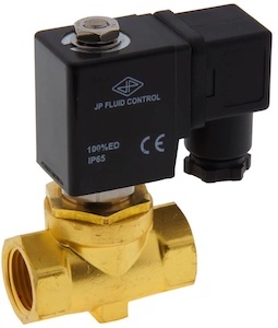
Figure 1: Solenoid valve
Solenoid valves control the flow of fluids in industrial and automation systems. The reliability and performance of solenoid valves are critical for ensuring these systems' safety, efficiency, and quality. Therefore, it is essential to test the solenoid valves thoroughly before installing or using them. Testing a solenoid valve involves checking its electrical and mechanical components, including the solenoid coil and the valve itself. This article discusses the essential components and testing procedures, including how to check the solenoid coil and the valve.
Table of contents
- When to test a solenoid valve
- How to test a solenoid valve coil with a multimeter
- Solenoid valve functional testing
- FAQ
View our online selection of solenoid valves!
When to test a solenoid valve
It is crucial to test solenoid valves to ensure they are functioning correctly and to avoid any potential issues that may cause system failures or safety hazards. Test a solenoid valve in the following situations:
- during installation
- after maintenance
- before commissioning
- suspected problems, such as a leak or a malfunction, in the system
How to test a solenoid valve coil with a multimeter
- Wear protective equipment (i.e., insulated gloves and eyewear) to protect against shock hazards from the live voltage supplied to the solenoid during diagnosis.
- Disconnect the solenoid from any electrical connections or wiring attached to it.
- Check the solenoid manufacturer's specifications to determine its supply voltage (AC/DC).
- Connect the solenoid terminals to the required power source. For this, connect the positive terminal of the power source to one of the solenoid terminals and the negative terminal of the power source to the second terminal of the solenoid. This should bring continuity across its terminals.
- Once the solenoid is connected to the power source, the circuit closes, and the solenoid should activate. There should be a click from the solenoid once the current is properly supplied. If there isn't a click, the solenoid coil is bad, and the solenoid needs to be changed. To diagnose the solenoid, use a multimeter to test the solenoid for its resistance and voltage. Both methods are discussed in greater detail below.
Resistance testing
A resistance test ensures that the circuit within the solenoid is good condition.
- Set the multimeter's dial to measure resistance, represented by the Ω symbol on the meter.
- Place the probes: The solenoid typically has three terminals; one is usually a peculiar-looking ground connection, while the other two look alike and are to be tested (or check the manufacturer's manual to determine the terminals correctly). To test the solenoid, connect the multimeter probes to these terminals, ensuring that the connections are properly in contact with the terminals.
-
Note the multimeter readings:
- The resistance reading can vary depending on the specific solenoid valve. Consult the manufacturer's documentation to determine the expected resistance value range.
- An 'OL' reading (infinite resistance) on the multimeter signifies an incomplete circuit within the solenoid (maybe from a bad coil or wire), and the solenoid needs to be replaced.
Voltage testing
A voltage test ensures that the solenoid receives or works with the right amount of voltage supplied by a power source.
- Check the solenoid manual for specifications on whether the device works on AC or DC voltage. Rotate the multimeter dial and set it to measure AC (V~) or DC (V...) voltage.
- Connect the multimeter probes to the solenoid terminals
- Note the results. If the solenoid is operating normally, the multimeter reads a voltage that matches the rated voltage of the valve; otherwise, the coil is faulty and needs to be replaced.
- Turn off the power supply to the solenoid valve and disconnect the multimeter probes.
Shock protection
Disconnecting the power source after the test while still holding the solenoid terminal in each hand can result in an electric shock. This happens because the solenoid's inductance produces a high voltage when the current rapidly decays upon disconnection. To avoid this, use a switch in series (Figure 2 labeled B) to create a safer circuit. Alternatively, connect a reverse-biased diode (Figure 2 labeled D) across the solenoid to provide a path for the current to flow through the coil when the battery is disconnected. A reverse-biased diode is a diode that is operated with the polarity of its voltage source reversed. This is an optional step, but failure to do so may result in the generation of very high voltages, which can lead to sparks and other hazards.
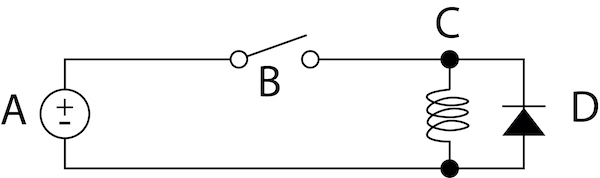
Figure 2: Solenoid shock protection circuit: power supply (A), switch (B), solenoid (C), and reverse-biased diode (D).
Solenoid valve functional testing
Functional testing ensures that the solenoid valve operates properly in its intended application.
- Check the manufacturer datasheet or instrument nameplate to confirm the solenoid valve's voltage and current ratings. In this example, assume that the solenoid valve is a +24V DC device.
- Check the solenoid valve port configuration, which can be either normally closed (NC) or normally open (NO). For this example, assume that the valve is NC.
- Hook up the instrument according to the typical test set-up shown in Figure 3.
- Connect the air supply (Figure 3 labeled A) to a pneumatic filter regulator (Figure 3 labeled B) to filter and regulate the air.
- Apply the specified air pressure to the solenoid valve's inlet port (Figure 3 labeled C), and connect the power supply to the valve terminals.
- Switch on the power supply, and monitor the test gauge pressure (Figure 3 labeled D) to confirm that the valve is energized (the pressure should increase).
- Switch off the power supply, and confirm that the valve is de-energized by checking the test gauge pressure again (the pressure should decrease).
- Tabulate all of the results in the check sheet to keep track of the testing procedure and its outcome. For example, If the pressure does not decrease when the power supply is switched off, the valve is not de-energized and may be stuck in the open position. This could be caused by a malfunction in the solenoid coil or by dirt or debris in the valve body obstructing the airflow. In such a case, disassemble the valve and inspect it for damage. Read our article on troubleshooting solenoid valves for more details.
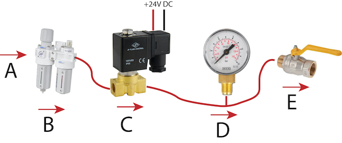
Figure 3: Solenoid valve functional testing: Air inlet (A), air filter regulator (B), solenoid valve (C), pressure gauge (D), and ball valve (E)
Read our humidifier, vacuum, and water solenoid valve articles for more details on the specific applications of solenoid valves and our solenoid valve parts article to know more about the valve parts in detail.
FAQ
How to test a solenoid valve with a multimeter?
Set the multimeter to measure resistance (ohms). Then, connect the multimeter probes to the two electrical terminals of the solenoid valve and check if the reading on the multimeter falls within the specified range for the valve.


