


How to Troubleshoot And Test A Transformer
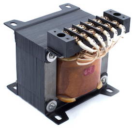
Figure 1: Transformer
Transformers play a vital role in electrical appliances. These devices follow the principle of impedance matching to efficiently transfer power from one circuit to another while reducing losses. However, a fault in these transformers can lead to critical problems for the system's operation. To avoid such risks of damage or malfunctioning, a proper follow-up of the maintenance schedule is recommended. This article illustrates the proper procedure for transformer troubleshooting and testing.
Table of contents
- Causes of transformer quality problems
- How to test a transformer
- Understanding transformer parameters
- Transformer Temperature-rise testing
- Other transformer tests
- FAQs
View our online selection of transformers!

Causes of transformer quality problems
Several factors can cause a transformer to go bad. To check if a transformer is bad, it's important to be familiar with common transformer failure symptoms such as overheating, insulation breakdown, and humming noises. To test a transformer, the common problems and their root causes should be identified. Then the right repair solution can be implemented. Here are some common transformer problems and their causes to keep in mind when troubleshooting or replacing a transformer:
Overheating
- Insulation breakdown: High temperatures can cause an insulation breakdown, leading to insulation failure. It can also create arcing conditions that damage connectors and cores. Electric arcing is when a part of a conductor melts and vaporizes. When the conductor cools, it contracts and creates an electric arc. Overheating can happen when high voltages flow through wires or conductors - like what happens with transformers with a short circuit or ground fault.
- Electromagnetic interference: The higher heating caused by the arcing will increase the electromagnetic interference and electrostatic voltages in the transformer. Electromagnetic interference can be caused by the switching of high-frequency currents, exciting the transformer's core. The interference leads to a disruption in the electromagnetic field and is often accompanied by electrostatic voltages.
- Transformer component failure: When a transformer overheats, the core may become brittle, the insulating oil can dry out and crack, and the windings can carry excessive currents and melt. In addition, the operating voltage is higher than usual. This causes high current stresses, leading to the early failure of components like bushings and terminal blocks. Read our electrical transformers article for more information on the various types of transformer cores.
Harmonics
Harmonics are simultaneous disturbances of the primary and secondary windings. Arcing conditions in the magnetic circuit can cause electromagnetic interference and electrostatic voltages. They mainly occur due to faults in the impedance matching circuit, leading to the loss of both primary and secondary currents (resulting from either an active or short-circuit fault). An impedance matching circuit is an electronic circuit that detects and compensates for the transformer's resistive, inductive, and capacitive reactance changes. It also minimizes losses due to electromagnetic interference and can reduce peak currents induced by harmonics.
Overloading
Overloading can lead to electrical breakdowns. The voltage and current levels created by overloading can lead to excessive heating in a transformer. Overloading occurs when the power supply does not provide enough capacity to move the required current through a transformer. To ensure a transformer will not overload, the required transformer capacity should be calculated. The losses caused by overloading can increase power supply voltage, which reduces system efficiency and causes overheating. Read our article on transformer sizing and calculator for more information on calculating a transformer’s rating and capacity.
Unbalance
A transformer can be unbalanced in two conditions:
- Overloaded transformer: Overloading occurs when the current in one transformer section is much higher than in other areas. It can cause high temperatures and excessive losses in the insulation, terminals, and windings. When the transformer is overloaded, it can generate electromagnetic interference and electrostatic voltages.
- Underloaded transformer: An under-loaded transformer is likely to experience a breakdown because of insufficient quiescent power or loss of power at high loads. A transformer is under-loaded when the load becomes too small to maintain the amount of energy that the unit requires. In some cases, the windings and coils can be safe from damage.
How to test a transformer
Whether troubleshooting a transformer or replacing one, knowing how to test a transformer is an integral part of the process. The three primary tests used to determine the condition of a transformer are the open-circuit test, short-circuit test, and measurements of winding resistance.
Open-circuit test
The connection setup for the open-circuit test for a transformer is shown in Figure 2. The various components used are:
- B: Autotransformer
- V: Voltmeter
- W: Wattmeter
- A: Ammeter
- T: Transformer under test
An autotransformer is a special type of transformer with a single winding and is highly effective in producing a regulated voltage. The output of an autotransformer can be tapped at various points to produce varied voltages. The autotransformer is connected to an AC voltage source, as seen in Figure 2. The output of the autotransformer is tapped and connected to the ends of a voltmeter. Then perform the following steps:
- Keep the secondary side of the transformer under test open-circuited.
- Slowly increase the applied voltage at the primary side till it reaches the rated voltage of the transformer. Keep checking the voltmeter during this phase.
- Once the rated voltage is reached (as indicated on the transformer’s label), record the readings of all three instruments, namely, voltmeter, ammeter, and wattmeter.
The ammeter gives the value of no-load current (as the secondary side is left open-circuited). The voltmeter reading is equal to the voltage induced on the secondary side of the transformer. The wattmeter reading gives the value of input power during the test. As the transformer is open-circuited, there is no current flow on the secondary side. Hence, the wattmeter reads the magnitude of core losses and copper losses occurring in the transformer. The no-load current is much less compared to the full-load current of the transformer; hence, the copper loss due to the no-load current can be neglected. Therefore, an open-circuit test gives the magnitude of core losses within the transformer. The core loss magnitude can be used to determine if there are any issues within the magnetic core of the transformer.
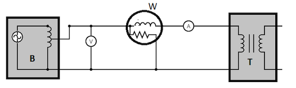
Figure 2: Open-circuit test transformer: autotransformer (B), voltmeter (V), wattmeter (W), ammeter (A), and transformer under test (T).
Short-circuit test
The connection setup for a short-circuit test is given in Figure 3. The various components used are:
- B: Autotransformer
- V: Voltmeter
- W: Wattmeter
- A: Ammeter
- T: Transformer under test
Perform the following steps to test the transformer:
- Short circuit the secondary side of the transformer.
- Apply a low voltage of 7-10 % of the transformer’s rated voltage at the primary side with the help of an autotransformer (Figure 3 labeled B). The output of an autotransformer can be tapped at various points to get different voltages.
- Slowly increase the applied voltage until the ammeter (Figure 3 labeled A) and wattmeter (Figure 3 labeled W) give a reading equal to the transformer’s rated current.
- Note the readings on the voltmeter, ammeter, and wattmeter.
The ammeter reading gives the primary side equivalent of the transformer’s full load current. As the applied voltage is very small compared to the rated voltage of the transformer, core losses can be taken as negligible. Therefore a short-circuit test measures the copper loss in a transformer. The value of copper loss can be used to determine if there is an issue with the transformer windings.
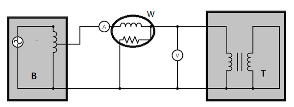
Figure 3: A short-circuit test transformer: autotransformer (B), wattmeter (W), voltmeter (V), ammeter (A), and transformer under test (T).
Resistance measurement
Measurement of a transformer’s winding resistance is essential to calculate the I2R losses in the transformer. The resistance value can also be used as a measure to diagnose possible damages.
A simple method to measure the transformer resistance is shown in Figure 4:
- T: Transformer under test. It has an effective inductance and a resistance value (to be computed during the test)
- R: An external resistance of known value
- V: Voltmeter
- A: Ammeter
- DC: DC voltage source
A known DC value is applied to the circuit, initiating a current flow. The voltage drop and the test current are measured, and the resistance is calculated. Read our article on low-voltage transformers to know how to test a transformer with a multimeter.
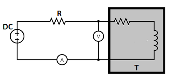
Figure 4: Resistance measurement: voltage source (DC), resistor (R), ammeter (A), voltmeter (V), and transformer under test (T).
Understanding transformer parameters
Before measuring the parameters of a transformer, you must first determine what you need to measure. Here are some terms you will encounter:
Primary current
The primary current is the direct output from primary windings and usually indicates how well the transformer performs. An increase implies that more power is transferred through the secondary winding and shows a suitable transformer. A decrease in primary current can also mean that a faulty or poorly configured impedance matching circuit is at play.
Secondary voltage
Secondary voltage is the output from the secondary winding and is usually an indication of the secondary circuit's condition of wiring and insulation. A low value indicates a poorly configured impedance matching circuit, among other things. A high value can indicate contamination from arcing or being shorted out by blockages or shorts, among other things.
Leakage inductance
The leakage inductance is the amount of current that can flow in the winding when no voltage is applied. A high leakage inductance can cause the transformer to have a short operation at high frequencies. Such transformers primarily work in short-circuiting applications to provide faster firing pulses, such as controlled detonation devices (CDDs) and capacitive effects.
Winding capacitance
Winding capacitance refers to the amount of current and voltage needed to charge and discharge the secondary through the circuit. The additional amount of current and voltage required to maintain the winding depends on whether the circuit has significant resistance. A high capacitance value can cause your transformer to work at higher frequencies and reach saturation at lower voltages.
Transformer temperature-rise testing
The most common parameter to check is the output power factor when testing a transformer. The output power factor is a ratio of input and output voltages that assesses the real power drawn by the load. It helps determine how well a transformer performs and whether it performs efficiently according to the manufacturers' specifications.
Actual load method
This test works best on low-capacity transformers. It measures the power factor at the actual load value. The load must have a high impedance and a very low reactance for this test to work accurately.
Loading-back method
This test helps to measure the power factor at no-load values. It provides a good approximation of high-capacity transformers and is more reliable than the actual load method.
Equivalent load method
This test can measure the rise in temperature of the windings in a transformer. It uses a calculated short-circuited current to measure the power factor at equivalent power requirements. It is essential to test transformers used in industrial applications where the AC voltage can be pretty high.
Other transformer tests
There are plenty of transformer testing methods to measure the resistance of a transformer to weather and diagnose faults or problems. These tests are not considered specific tests by a technician but are mostly part of the transformer's overall maintenance and testing program. Such include the no-load-loss testing (NLTL), which checks the transformer's output at no-load values. No other test checks the amount of power loss in a transformer more precisely than this method.
FAQs
What are the uses of transformers?
Transformers are used for voltage and current transformation, depending on the electricity used in the power systems. They can work as isolation transformers, autotransformers, step-downers, and step-up transformers.
What causes a transformer to burn out?
Transformers burn out due to over-heating caused by excessive current flow or short circuits. These conditions may occur due to poor connections and loose connections in the circuit, among other things.
What should you do when a transformer is burning?
Please stay away from it, as it could explode. Remove any combustible materials near it and then wait for the fire brigade to come and put out the flame.