


What Is a Butterfly Valve?
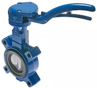
Figure 1: Butterfly valve
Butterfly valves are quarter-turn valves that are popular for on-off or modulating services. They are lightweight, do not take up much space, quick operation, and are available in large orifice sizes. The "butterfly" is a disk connected to a rod. When the valve opens, the disk rotates, allowing fluid to pass through. It closes when the rod rotates the disc by a quarter turn to a position perpendicular to the flow direction. In this article, you will learn how a butterfly valve works, the different types of butterfly valves, what actuation options are available for these valves, and more.
Table of contents
- Butterfly valves vs other valve types
- How does a butterfly valve work?
- Butterfly valve connection types
- Butterfly valve actuation
- Selection criteria
- Butterfly valve symbol
- FAQs
Butterfly valves vs other valve types
Choosing a butterfly valve over other types of valves can be advantageous for several reasons:
- Compact design: Butterfly valves are compact and lightweight, making them ideal for applications where space is limited. This is particularly beneficial in large piping systems where weight and space are critical factors.
- Cost-effectiveness: Butterfly valves are generally more cost-effective than other valve types, especially in larger sizes. Their simpler design and fewer components contribute to lower manufacturing and maintenance costs.
- Quick operation: Like ball valves, butterfly valves are quarter-turn valves that allow rapid opening and closing. This makes them suitable for applications requiring quick shut-off or frequent operation.
- Flow control: The angle of the disc controls the flow rate through the valve.
- Wide range of sizes: Butterfly valves are available in a wide range of sizes, suitable for both small—and large-scale applications.
Learn about the other valve types in our valve overview article.
How does a butterfly valve work?
A butterfly valve is a quarter-turn valve, meaning the handle (Figure 2 labeled A) needs to be turned 90° to open or close the valve fully. The handle turns the stem (Figure 2 labeled B), which rotates the disc (Figure 2 labeled D). When the valve closes, the disc presses against the seal (Figure 2 labeled E).
Additionally, the angle of the disc impacts the flow rate through the valve. This makes the butterfly valve an excellent choice for flow control beyond on/off control. Figure 2 demonstrates typical butterfly valve components.
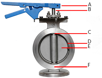
Figure 2: Butterfly valve diagram of butterfly valve parts: handle (A), stem (B), connection (wafer or lug) (C), disc (D), and seal (E).
Butterfly valve connection types
Butterfly valves can connect to a piping system in different ways. Two common connections are wafer and lug types. The most important difference between the two is that lug type butterfly valves are suitable for end-of-line services and isolation, whereas wafer type butterfly valves are not.
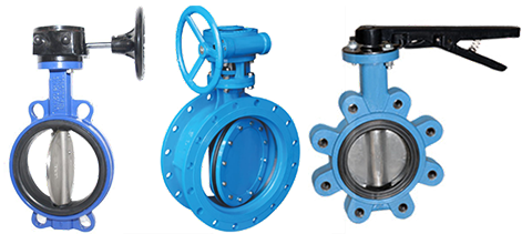
Figure 3: Butterfly valve connection types: wafer type (left) and lug type (right).
Wafer type butterfly valve
Wafer type butterfly valves (Figure 3 left) generally have four holes that line up with the pipeline connection. They fit snugly between flanges on the pipeline, and their rubber seal provides a strong seal between the valve and flange. As seen in Figure 4, bolts threaded on both ends pass through the holes in the valve and are secured to the pipeline with a nut on each side. Wafer type butterfly valves cannot be used for end-of-line service or isolation needs. For maintenance, the entire line needs to be shut down.
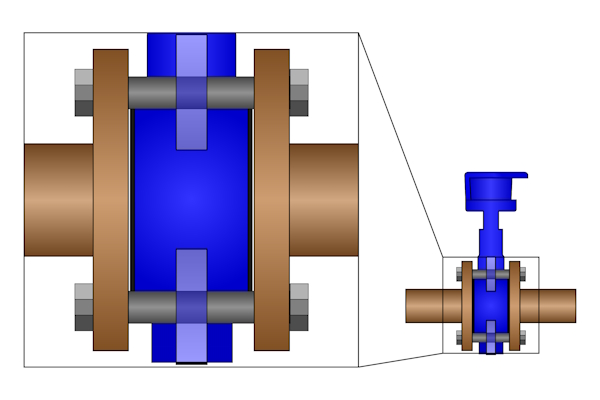
Figure 4: Bolts threaded on both ends pass through the holes on the butterfly valve.
Lug type butterfly valve
Lug style butterfly valves typically have four or more threaded holes on each face. As seen in Figure 5, bolts on both sides of the valve go through connection holes on the pipeline flange and into the threaded holes on the valve. This connection style allows lug type butterfly valves to be suitable for end-of-line services. Additionally, one side of the pipeline can be isolated and disconnected from the valve without shutting down the whole line. A blind flange is recommended when using a lug-type butterfly valve for end-of-line services.
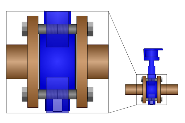
Figure 5: Bolts connect the lug type butterfly valve to the pipeline on both ends.
Butterfly valve actuation
Butterfly valves can be operated manually using handles and gears or automatically using electric or pneumatic actuators. Below is a brief description of the different types of actuation methods.
Manual butterfly valves
Manually actuated butterfly valves are inexpensive and easy to operate. The two common methods are:
- Squeeze lever: A squeeze lever is common for small butterfly valves. The handle has a locking detent that locks the valve into an open, partially open, or closed position. An example can be seen in Figure 4 (left).
- Hand wheel and gearbox: These are for larger butterfly valves. They utilize a gearbox to increase torque at the expense of decreased speed of opening/closing. Gear-operated valves are also self-locking (cannot be back-driven) and can be equipped with position indicators. An example can be seen in Figure 4 (right).
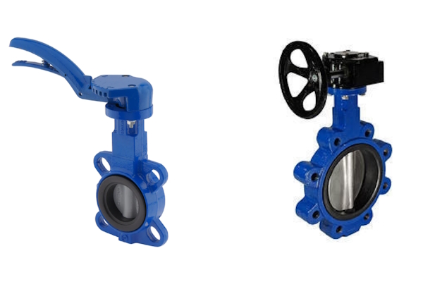
Figure 6: Manually actuated butterfly valves: squeeze lever (left) and hand wheel plus gearbox (right).
Automatic butterfly valves
Automatic butterfly valve refers to butterfly valves that are not manually actuated (i.e., electric and pneumatic butterfly valves). The actuators for these valves typically have manual override features and position indicators on top.
Electric butterfly valves
Electric butterfly valve refers to a regular butterfly valve with an electric actuator instead of a squeeze lever or hand wheel. Electric actuators can be quickly integrated into a system for automation because they are simple to install and wire. It's common for these actuators to use ISO 5211 flanges to mount onto the valve stem and shaft.
Electric butterfly valves are commonly used in pharmaceutical, chemical, and other industries. They close relatively slowly to mitigate water hammer and do not consume energy when the disc is not moving.
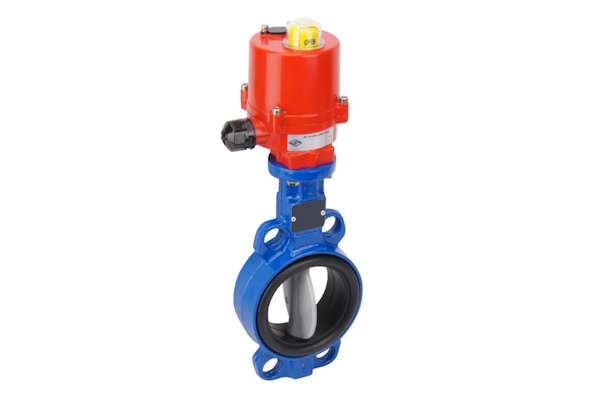
Figure 7: An electric butterfly valve
Pneumatic butterfly valves
Pneumatic butterfly valves use a pneumatic rotary actuator to operate the butterfly valve. For simple installation, pneumatic actuators can have an ISO 5211 flange for mounting to the butterfly valve and a NAMUR interface for mounting the solenoid valve.
Like their electric counterparts, pneumatic butterfly valves are found in various industries. Their primary advantages over electric actuators are that they operate significantly faster and often can be used in environments where explosions might happen. Note: Not every pneumatic actuator has approval (e.g., ATEX) for explosive environments.
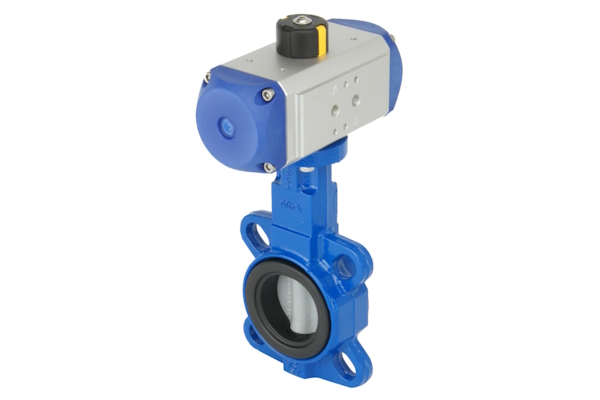
Figure 8: A pneumatic butterfly valve
Selection criteria
Consider the following criteria when selecting a butterfly valve:
-
Actuation
- Manual: Straightforward, inexpensive, and does not require power
- Electric: Precise, slow operating, and the most expensive option
- Pneumatic: Fast operating, potentially suitable for explosive environments
- Nominal inner diameter: One primary advantage of butterfly valves is that they range from very small to very large. For example, they can range from 1" to 28" (DN 25 to DN 700).
- Voltage: For electric butterfly valves, ensure the actuator matches the power supply. Electric actuators can work with DC or AC at various voltages.
- Connection: Choose between lug type and wafer type depending on whether you need end-of-line service or not, respectively.
-
Housing material
- Cast iron: Cast iron butterfly valves can work under a wider temperature range than stainless steel butterfly valves.
- Stainless steel: Stainless steel butterfly valves are typically selected for sanitary applications (e.g., food industry).
-
Seal material
- EPDM: EPDM works up to 120 °C (248 °F) and is the preferred choice for drinking water applications because it does not influence the water's taste.
- FKM: FKM works up to 180 °C (356 °F)
- NBR (nitrile rubber): NBR works up to 85 °C (185 °F)
- NBR (contains carboxyl): NBR containing carboxyl works up to 110 °C (230 °F)
- EPDM white: EPDM white works up to 80 °C (176 °F)
- PTFE/Silicone: PTFE/Silicone works up to 200 °C (392 °F)
- Material guide: Read our chemical resistance of materials guide to learn more.
- Max actuator torque: For automatic butterfly valves, ensure the actuator produces enough torque to efficiently open and close the butterfly valve. Read our guide to torque estimation in quarter turn valves to learn more.
- Safety function: Electric butterfly valves can be normally open or normally closed. Select based on what position the valve should have in the case of power loss or air supply loss.
- Max pressure difference at 20 °C (68 °F): Select a valve that can withstand the pressure coming through it. Typical values range from 6 to 16 bar (87 to 232 psi).
- Approval: Some applications require valves with approvals (e.g., drinking water applications and applications with explosive potential).
Butterfly valve symbol
The butterfly valve symbol closely resembles the actual valve. Two sideways T's represent the pipe and flange connections, and a diagonal line with a sphere in its center represents the valve's disc.
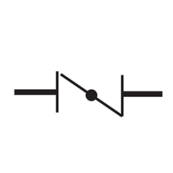
Figure 9: Butterfly valve symbol
FAQs
What is a butterfly valve used for?
Butterfly valves are used for on-off or modulated fluid control in various industrial applications.
Can you use a butterfly valve for gas?
Yes, butterfly valves can be used for liquids and gasses, but not bulk solids.
What is the advantage of a butterfly valve?
Butterfly valves are lightweight, especially at large sizes, and can be used for both on-off and modulated fluid control.
Can a butterfly valve be used for flow control?
Yes. There is a relationship between the angle of the disc and flow rate. It is not a linear relationship but the manufacturer's datasheets should offer guidance on the relationship.
Can a butterfly valve be installed upside down?
Technically a butterfly valve can be installed upside down. However, this is not recommended because it can negatively impact the seals and increase turbulence through the valve.
Do butterfly valves have a flow direction?
Yes. Butterfly valves have a flow direction. There may be an arrow stamped on the valve's body to indicate the direction.
Do butterfly valves need gaskets?
Many butterfly valves have resilient seats built in and do not require gaskets. However, butterfly valves with metal seats will require gaskets.


