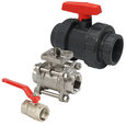
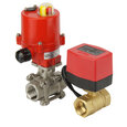
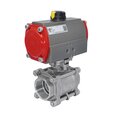
A Comprehensive Guide To Sizing Ball Valves
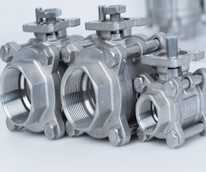
Figure 1: Ball valves with different orifice sizes
Understanding ball valve sizing is essential for industries using fluid control systems. There are many parameters to consider when sizing a ball valve, including the fluid type, flow rate, pressure, velocity, and operating conditions. This article comprehensively discusses ball valve sizing, including the key factors to consider, different methods, and sizing charts for common applications. Read our ball valve overview article for more information on the design and working of ball valves.
Table of contents
View our online selection of ball valves!
How to size ball valves
There are essential considerations to make when sizing ball valves for various applications, including pressure parameters, valve-to-pipe size relationships, valve connections, media velocity, and concerns about cavitation.
Flow considerations
When sizing ball valves for various applications, it's essential to consider the flow rates, often represented by the Cv and Kv values. These values indicate the valve's flow capacity, essentially describing how much fluid can pass through the valve under a given pressure. A higher Cv or Kv value means the valve can pass more fluid with less resistance, thus offering better flow control. Here are some flow considerations to remember:
- Maximum flow when about 90% open: This ensures that the valve is not operating at its limit, which can help prevent wear and tear and extend its lifespan.
- Minimum flow when about 10% open: This provides control and allows low flow rates while the valve is barely open, which could cause instability or inaccurate control.
- Normal flow when about 60-70% open: This provides a balance between control and lifespan, as operating the valve in this range allows for some adjustment in either direction without pushing the valve to its limits.
Pressure
- Design the valve to use 10-15% of the total pressure drop or 0.7 bar (10 psi), whichever is greater. This allows the valve to handle pressure changes in the system without risk of damage or failure.
- Size control valves to absorb about 1/3rd of the total system pressure drop at max flow. This pressure drop distribution allows the control valve to effectively regulate the flow while ensuring that the system operates efficiently and safely.
- Set the control pressure drop to 50-60% of the frictional pressure loss of the piping systems. The pressure drop refers to the reduction in pressure as fluid passes through the valve. By setting this to 50-60% of the frictional pressure loss of the piping systems, the valve can effectively manage the flow without causing an excessive decrease in pressure that could hamper the system's efficiency.
Relation to pipe size
- Control valves should not be sized less than half the pipe size. This ensures that the valve can accommodate the required flow rate without causing a substantial pressure drop or high-speed flow, which could lead to issues such as cavitation or noise.
- Valves for shutoff purposes should be the same size as the pipe (also known as line size). This ensures minimal disruption to the flow when the valve is fully open.
- Never use a ball valve larger than the pipe it will be installed in. A larger valve may not fit properly, could disrupt the flow dynamics, and cause an excessive pressure drop or other operational issues.
Valve connections
Flanged connections are common and are typically used per the line's specifications. However, for ball valves with a diameter of 1½ inches or less, a minimum rating of 300 ANSI (American National Standards Institute) is recommended, as these valves are used in high pressure applications, such as oil and gas production, chemical processing, and power generation. The ANSI 300 rating indicates that the valve can handle a maximum pressure of 49.6 bar (720 psi) at ambient temperature.
Media velocity
A line velocity of about 3 m/s (10 ft/s) is recommended for non-abrasive, clean liquids. However, it is crucial to keep the velocity as low as possible for abrasive fluids to minimize wear and tear on the valve. The velocity should still be high enough to prevent the abrasive particles from settling out of the fluid. Read our valves for high viscosity fluids article for more details.
It's recommended to have a straight section of pipe after the valve to prevent cavitation. Cavitation refers to the forming and collapsing of vapor bubbles in a fluid, which can damage the valve. This allows the fluid to flow smoothly, reducing the likelihood of disruption. A 'T' junction or elbow immediately after the valve can disrupt the flow and lead to cavitation.
How to measure ball valve size
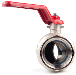
Figure 2: Ball valve bore
Use our Kv or Cv calculator to calculate the flow rate required for a given medium and pressure drop. When choosing valves, select a Cv (or Kv) value closest to the calculated result, typically rounding down to the nearest number unless a specified maximum pressure differential of a valve is exceeded. An oversized valve can cause water hammer and premature wear on the valve packaging. Conversely, an undersized valve may not provide enough media flow and exceed the available differential pressure between the ports.
Table 1 shows the Cv and Kv values against the standard ball valve sizes for three-way reduced port threaded ball valves. If the calculated Cv value is 15, choose a ball valve with ½ inch size as it is closest to the rated Cv value (15.2) for the size. If the calculated Cv value is 110, choose a ball valve size of 2 inches, and so on.
Ball valve size chart
The Cv and Kv values of different types of ball valves are given in Tables 1-5.
Full port ball valve Cv chart & Kv chart
Table 1: Full port ball valve size chart in mm (Cv chart)
| Size BSP (in inch) | DN (mm) | Cv when fully open | Kv, when fully open |
| 1/4 | 8 | 18 | 15.35 |
| 3/8 | 10 | 20 | 17.06 |
| 1/2 | 15 | 23 | 19.6 |
| 3/4 | 20 | 55 | 46.9 |
| 1 | 25 | 95 | 81.03 |
| 1 1/4 | 32 | 155 | 132.2 |
| 1 1/2 | 40 | 260 | 221.8 |
| 2 | 50 | 440 | 375.3 |
| 2 1/2 | 65 | 710 | 605.6 |
| 3 | 80 | 1050 | 895.6 |
| 4 | 100 | 2040 | 1740.1 |
3-way full bore flanged ball valve Cv & Kv chart
Table 2: 3-way full bore ball valve Cv chart
| Size (in inch) | Size (in mm) | Cv | Kv (m3/h) |
| 1/2 | 12.7 | 15.2 | 13 |
| 3/4 | 19 | 23.3 | 20 |
| 1 | 25.4 | 45.5 | 39 |
| 1 1/4 | 31.75 | 58.4 | 50 |
| 1 1/2 | 38.1 | 112 | 96 |
| 2 | 50.8 | 224.1 | 192 |
| 2 1/2 | 63.5 | 308.1 | 264 |
| 3 | 76.2 | 409.6 | 351 |
| 4 | 101.6 | 762.1 | 653 |
3-way reduced port threaded ball valve Cv and Kv chart
Table 3: 3-way reduced port threaded ball valve Cv and Kv chart
| Size (in inch) | Size (mm) | Cv (gallons/min) | Kv (m3/h) |
| 1/4 | 6.35 | 12.8 | 11 |
| 3/8 | 9.525 | 12.8 | 11 |
| 1/2 | 12.7 | 15.2 | 13 |
| 3/4 | 19.05 | 17.5 | 15 |
| 1 | 25.4 | 36.2 | 31 |
| 1 1/4 | 31.75 | 45.5 | 39 |
| 1 1/2 | 38.1 | 72.4 | 62 |
| 2 | 50.8 | 120.2 | 103 |
| 2 1/2 | 63.5 | 239.2 | 205 |
| 3 | 76.2 | 270.7 | 232 |
| 4 | 101.6 | 480.8 | 412 |
V-port ball valve Cv chart
A V-port ball valve has a contoured V-shaped ball inside that precisely controls flow rates in industrial applications.
Table 4: V-port ball valve Cv dimension chart
|
Valve size (inch) |
Valve size (mm) | Ball angle | 15% | 20% | 30% | 40% | 50% | 60% | 70% | 80% | 90% | 100% |
1/2 |
12.7 |
30° | 0.1 | 0.1 | 0.2 | 0.3 | 0.5 | 0.8 | 1.1 | 1.6 | 2.2 | 2.6 |
| 60° | 0.1 | 0.1 | 0.3 | 0.5 | 0.9 | 1.4 | 2 | 3.3 | 4.4 | 6 | ||
3/4 |
19.05 |
30° | 0.1 | 0.2 | 0.5 | 0.7 | 1.1 | 1.8 | 2.4 | 3.3 | 4.5 | 5.4 |
| 60° | 0.1 | 0.2 | 0.7 | 1 | 1.7 | 2.8 | 4 | 6.5 | 9 | 12 | ||
1 |
25.4 |
30° | 0.1 | 0.3 | 0.8 | 1.3 | 2.3 | 3.5 | 5.1 | 9.8 | 8.5 | 10 |
| 60° | 0.2 | 0.4 | 1.1 | 1.8 | 3.4 | 5.3 | 7.9 | 12.3 | 15.3 | 21 | ||
1 1/4 |
31.75 |
30° | 0.2 | 0.4 | 1.1 | 2 | 3.7 | 5.5 | 8 | 10 | 13 | 15 |
| 60° | 0.2 | 0.6 | 1.8 | 3 | 5.5 | 9.5 | 12.8 | 19 | 26 | 39 | ||
1 1/2 |
38.1 |
30° | 0.3 | 0.6 | 1.6 | 3 | 5 | 7.5 | 11 | 14 | 17 | 20 |
| 60° | 0.4 | 0.8 | 2.5 | 4 | 8 | 13 | 19 | 27 | 40 | 52 | ||
2 |
50.8 |
30° | 0.4 | 1.2 | 3.8 | 6 | 10 | 15 | 23 | 31 | 43 | 60 |
| 60° | 0.4 | 1. | 4.6 | 9 | 16.5 | 27 | 39 | 55 | 83 | 110 | ||
2 1/2 |
63.5 |
30° | 0.4 | 1 | 4 | 8 | 12 | 18 | 28 | 37 | 62 | 75 |
| 60° | 0.4 | 1.5 | 5 | 10 | 21 | 34 | 53 | 75 | 103 | 150 | ||
3 |
76.2 |
30° | 0.5 | 1.2 | 4 | 8 | 14 | 23 | 33 | 46 | 65 | 82 |
| 60° | 0.5 | 2.5 | 6 | 4 | 25 | 40 | 65 | 91 | 128 | 165 | ||
4 |
101.6 |
30° | 0.6 | 2 | 6 | 15 | 29 | 48 | 71 | 100 | 130 | 159 |
| 60° | 0.7 | 3 | 11 | 25 | 40 | 59 | 90 | 141 | 212 | 356 | ||
6 |
152.4 |
30° | 0.9 | 3.2 | 14 | 33 | 60 | 103 | 155 | 220 | 280 | 350 |
| 60° | 2 | 5 | 22 | 60 | 110 | 190 | 285 | 416 | 586 | 800 |
V port ball valve Kv chart
Table 5: V-port ball valve Kv dimension chart
|
Valve size (inch) |
Valve size (mm) | Ball angle | 15% | 20% | 30% | 40% | 50% | 60% | 70% | 80% | 90% | 100% |
1/2 |
12.7 |
30° | 0.08 | 0.08 | 0.17 | 0.25 | 0.42 | 0.68 | 0.93 | 1.36 | 1.87 | 2.2 |
| 60° | 0.08 | 0.08 | 0.25 | 0.43 | 0.77 | 1.19 | 1.706 | 2.8 | 3.7 | 5.12 | ||
3/4 |
19.05 |
30° | 0.08 | 0.17 | 0.42 | 0.6 | 0.93 | 1.5 | 2.04 | 2.8 | 3.8 | 4.6 |
| 60° | 0.08 | 0.17 | 0.59 | 0.85 | 1.45 | 2.4 | 3.412 | 5.5 | 7.7 | 10.23 | ||
1 |
25.4 |
30° | 0.08 | 0.25 | 0.68 | 1.1 | 1.96 | 2.98 | 4.3 | 8.3 | 7.25 | 8.53 |
| 60° | 0.17 | 0.34 | 0.93 | 1.5 | 2.9 | 4.5 | 6.73 | 10.5 | 13.05 | 17.91 | ||
1 1/4 |
31.75 |
30° | 0.1 | 0.34 | 0.94 | 1.7 | 3.16 | 4.7 | 6.82 | 8.53 | 11.1 | 2.8 |
| 60° | 0.17 | 0.51 | 1.53 | 2.6 | 4.7 | 8.1 | 10.9 | 16.2 | 22.1 | 33.3 | ||
1 1/2 |
38.1 |
30° | 0.25 | 0.51 | 1.36 | 2.5 | 4.2 | 6.4 | 9.4 | 11.9 | 14.5 | 17.06 |
| 60° | 0.34 | 0.68 | 2.13 | 3.4 | 6.8 | 11.1 | 16.2 | 23.03 | 34.12 | 44.3 | ||
2 |
50.8 |
30° | 0.34 | 1.02 | 3.24 | 5.1 | 8.5 | 12.8 | 19.6 | 26.4 | 36.7 | 51.2 |
| 60° | 0.3 | 0.8 | 3.9 | 7.7 | 14.07 | 23.03 | 33.2 | 46.9 | 70.7 | 93.8 | ||
2 1/2 |
63.5 |
30° | 0.3 | 0.8 | 3.4 | 6.8 | 10.2 | 15.3 | 23.9 | 31.5 | 52.9 | 63.9 |
| 60° | 0.3 | 1.3 | 4.3 | 8.5 | 17.9 | 29 | 45.2 | 64 | 87.8 | 127.9 | ||
3 |
76.2 |
30° | 0.4 | 1 | 3.4 | 6.8 | 11.9 | 19.6 | 28.1 | 39.2 | 55.4 | 69.9 |
| 60° | 0.4 | 2.1 | 5.1 | 3.4 | 21.3 | 34.1 | 55.4 | 77.6 | 109.2 | 140.7 | ||
4 |
101.6 |
30° | 0.5 | 1.7 | 5.1 | 12.8 | 24.7 | 40.9 | 60.5 | 85.3 | 110.9 | 135.6 |
| 60° | 0.6 | 2.55 | 9.4 | 21.3 | 34.1 | 50.3 | 76.8 | 120.3 | 180.8 | 303.6 | ||
6 |
152.4 |
30° | 0.7 | 2.73 | 11.9 | 28.1 | 51.2 | 87.8 | 132.2 | 187.7 | 238.8 | 298.5 |
| 60° | 1.7 | 4.3 | 18.7 | 51.2 | 93.8 | 162 | 243.1 | 354.8 | 499.8 | 682.4 |
FAQs
What is valve sizing?
Valve sizing is selecting the appropriate valve dimensions and characteristics to ensure it can effectively control fluid flow within a piping system based on specific application requirements.
How do you size a ball valve?
Sizing a ball valve involves considering factors such as flow rates, pressure drop, pipe size, and application-specific requirements to select the appropriate valve size and configuration that can effectively control fluid flow within a system.
What is the Cv of a ball valve?
The Cv (flow coefficient) of a ball valve represents its ability to control fluid flow through it and is typically provided by the valve manufacturer as a numerical value, with higher Cv values indicating greater flow capacity.
How to calculate Cv for valves?
Cv (flow coefficient) for valves is calculated using: Cv = Q / sqrt(deltaP). Q is the flow rate in GPM, deltaP is the pressure drop in psi.
How to measure valve size?
To measure valve size, determine the nominal pipe size (NPS) or diameter of the valve's inlet/outlet connection using a tape measure or calipers. Common NPS sizes include 1/2", 3/4", and 1".


