Globe Valve vs Ball Valve
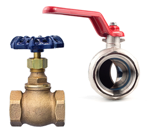
Figure 1: Globe valve (left) and ball valve (right)
Globe valves and ball valves are both shut-off valves typically used in piping systems. However, it is usually not immediately obvious which valve is most suitable for an application. System design should be finished before valve selection in order to select the best valve for the job in terms of cost, installation space, flow control, and more. Keep reading to learn more about how a globe valve may be more suitable than a ball valve and vice versa.
Table of contents
- Working principles
- Flow control
- Head loss
- Valve design
- Symbols
- Applications
- Globe valve and ball valve similarities
- Pros and cons of ball valves and globe valves
- Globe valve and ball valve selection
- FAQs
View our online selection of globe and ball valves!
Working principles
Globe valve working principle
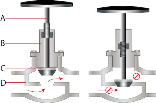
Figure 2: A globe valve in the open position (left) and the closed position (right) with the valve stem (A), bonnet (B), plug (C), and body (D).
A globe valve is a multi-turn valve, meaning that the handwheel needs to be turned more than 360° to fully open or close the valve. The main components of a globe valve are the valve body, bonnet, handwheel, stem, and plug. Media flows into the valve body (Figure 2 labeled D) through an inlet and exits the valve body through an outlet. The bonnet (Figure 2 labeled B) protects the threaded components of the valve and attaches to the valve body. As the user turns the handwheel, it turns the threaded stem (Figure 2 labeled A), which raises or lowers the plug (Figure 2 labeled C). Raising the plug opens the orifice, thereby allowing media flow. Lowering the plug into the valve seat seals the orifice, preventing the flow. Raising the disc, on the other hand, increases the flow rate. The flow rate is maximum when the disc is raised to its maximum position. The fluid flow rate is controlled by moving the disc proportionally through the stem.
Ball valve working principle
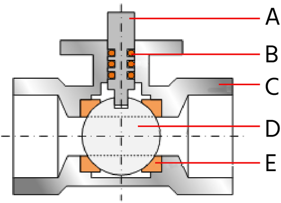
Figure 3: Ball valve parts; Stem (A), o-rings (B), body (C), ball (D), and seat (E)
A ball valve is a quarter-turn valve, meaning that the handle only needs a 90° turn to fully open or close the valve. The main components of a ball valve are shown in Figure 3. The stem (Figure 3 labeled A) connects to the ball (Figure 3 labeled D). The ball sits on the ball valve seat (Figure 3 labeled E), creating the seal. O-ring stem seals (Figure 3 labeled B) are used to prevent leakage. All of these components are within the valve housing (Figure 3 labeled C). As seen in Figure 3, the ball has a bore running through it. Under normal operation, the bore is either aligned with the valve ports to allow flow, or perpendicular to the ports to block flow. Read our article on ball valves for more details on how they work.
Flow control
Globe and ball valves are both used to turn on or off the flow. Globe valves, though, can also function in a partially open or closed state to modulate the flow. This flow regulation is achievable due to the globe valve’s disc sitting parallel to the flow. The linear flow rate achieved by globe valves is higher than that achieved by ball valves, and reduces the effects of water hammer.
Head loss
Globe valves have significantly higher pressure loss (head loss) in the fully open position than ball valves. This is because the fluid has to change direction multiple times as it passes through a globe valve.
Valve design
Globe valve design
Globe valves are available in three basic configurations: T- or Z globe valve, Y-globe valve, and angle globe valve. Read our article on globe valves for more information on each type.
Ball valve design
The ball valve can be classified into different categories depending on its housing structure, ball design, and port size. Depending on the housing structure, we can have 1, 2, or 3-piece ball valves. Depending on the port size, ball valves are categorized as full port ball valves, standard port ball valves, or reduced port ball valves. And depending on the number of ports, ball valves are classified into 2-way and multiport valves.
Symbols
- Figure 4 shows the symbols for various globe valve configurations.

Figure 4: Globe valve symbols: globe (A), hand operated (B), pneumatic (C), motor operated (D), hydraulic operated (E).
The symbols for a ball valve are shown in Figure 5. For more details on the symbols of various ball valve configurations, read our article on ball valve symbols.

Figure 5: Actuated ball valve symbols; manually operated ball valve (A), pneumatically actuated ball valve (diaphragm type) symbol (B), pneumatically actuated ball valve (rotary piston type) symbol (C), electrically actuated ball valve symbol (D), and a hydraulic actuator ball valve symbol (E).
Applications
Globe valves are used to control fluid flow. Furthermore, globe valves are advantageous in applications requiring precise throttling. Ball valves, on the other hand, are commonly used for plumbing system shut-off and isolation. Industrial applications for globe valves include fuel oil systems and cooling water systems, while those of ball valves include chemical storage and natural gas industries.
Globe valve and ball valve similarities
Globe valves and ball valves share some similarities. Both valves are used in piping systems to control the flow of liquids and gasses. Both are shut-off valves designed to allow or block the fluid flow within a pipe. Globe valves and ball valves can be operated manually or automatically.
Pros and cons of ball valves and globe valves
- Operation: Ball valves are simple and easier to operate than globe valves.
- Throttling: Globe valves are suitable for throttling operations, whereas ball valves should be either fully shut or fully open.
- Handle: Ball valves are quarter-turn valves which means the ball valve handle must be turned by 90° to go from fully open to a fully closed state or vice versa. The handwheel of globe valves must be turned multiple times from entirely closed to fully opened. Learn more in our valve handle types article.
- Cost: Due to their simple structure, ball valves are cheaper than globe valves.
- Space: Globe valves occupy more space compared to ball valves.
- Pressure rating: Ball valves can handle higher pressure than globe valves.
- Durability: Ball valves are longer-lasting than globe valves.
- Leakages: Globe valves are more prone to leakages than ball valves.
- Media flow resistance: A globe valve offers more resistance to media flow compared to ball valves.
- Head loss: Globe valves have a higher head loss than ball valves.
Globe valve and ball valve selection
The selection between a ball valve and a globe valve depends on the intended purpose. The main factors to consider during the selection process are discussed below:
- Flow rate: Ball valves are desirable in applications where a high flow rate is necessary due to their full-bore design.
- Pressure drops: Ball valves have lower pressure drops because flow moves straight through them.
- Maintenance: Ball valves are simple to maintain because the valve only needs a little lubrication to stay clean. Further maintenance is necessary upon debris buildup.
- Temperature: Ball valves function better under high-temperature conditions due to their durable construction.
FAQs
What are the typical applications of a globe valve?
Globe valves are used commonly to control water flow in irrigation systems, regulate airflow in AC systems, and control oil flow in pipelines.
What is the main difference between a ball valve and a globe valve?
The ball valve has a hollow ball that rotates inside the valve, whereas the globe valve has a disc that moves vertically through the valve stem.
Which valve is better between globe valves and ball valves?
This depends on the intended application. Globe valves are better for throttling applications, while ball valves offer better performance as shutoff valves.


