Pneumatic Solenoid Valve Diagrams
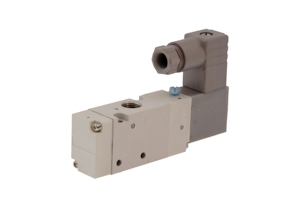
Figure 1: A pneumatic solenoid valve.
Understanding the diagrams of pneumatic solenoid valves is essential for designing, maintaining, or troubleshooting pneumatic systems. These valves control air or gas flow, enabling precise machinery operation. They use electromagnetic solenoids to open and close valve ports: an electrical current generates a magnetic field that moves a plunger or armature, regulating the flow. Pneumatic solenoid valves are used in various applications, from HVAC systems to complex manufacturing automation.
Table of contents
- Pneumatic solenoid valve diagrams
- Types of pneumatic solenoid valves
- Pneumatic solenoid valve applications
- FAQs
View our online selection of pneumatic solenoid valves!
Pneumatic solenoid valve diagrams
Diagrams of pneumatic solenoid valves visually represent their internal structure and operation. These diagrams are essential for several reasons:
- Design and installation: Engineers and technicians use these diagrams to accurately design and install pneumatic systems.
- Maintenance and troubleshooting: Understanding the diagrams helps diagnose issues and perform maintenance tasks efficiently.
- Safety: Proper interpretation of valve diagrams ensures that systems operate safely, preventing accidents and equipment damage.
How to read a diagram
If the diagram is vertical, the bottom square shows the unactuated state (Figure 2 labeled B), and the top square shows the actuated state (Figure 2 labeled A). If the diagram is horizontal, the right square is the un-actuated state, and the left square is the actuated state. The arrows show the direction of airflow, and the shapes that look like a T on its side show a port that is not being used in the valve's current state or is plugged entirely.
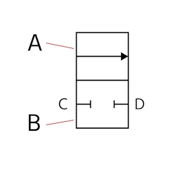
Figure 2: A pneumatic solenoid valve diagram with the actuated state (A), unactuated state (B), inlet (C) and outlet (D).
Other common symbols on a diagram are seen in Table 1. Learn more about symbols used in pneumatic system diagrams by reading our pneumatic system symbols overview.
Diagram numbers
Throughout this article, pneumatic diagrams are marked with numbers 1-5. They mean the following:
- In: Air flows into the valve at this port
- Out: Air flows out of the valve at this port to another system component. Or, air flows into this port from another system component to be exhausted through an exhaust port.
- Exhaust: Air exhausts at this port after returning to the valve from another system component
- Out: Air flows out of the valve at this port to another system component. Or, air flows into this port from another system component to be exhausted through an exhaust port.
- Exhaust: Air exhausts at this port after returning to the valve from another system component
Table 1: Common symbols indicating pneumatic solenoid valve actuation and return
| Name | Symbol | Explanation |
| Spring return | 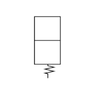 |
Diagonal lines at the top or bottom of the valve indicate a spring return |
| Air pilot | 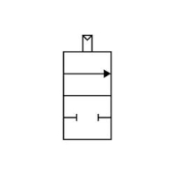 |
A rectangle with a triangle on one side represents an air pilot that assists in valve actuation |
| Manual actuation | 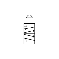 |
The rectangle and semicircle on top of the valve indicates that the valve is manually actuated |
| Limit switch valve | 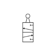 |
The circle and two lines on top of the valve indicate it is acting as a limit switch valve. |
Normally open vs normally closed valve diagrams
The unactuated state portion of the diagram helps a reader understand if the valve is normally open or normally closed. A normally open valve will show air moving from left to right when unactuated (Figure 3 left) and a normally closed valve will show air moving from right to left when unactuated (Figure 3 right).
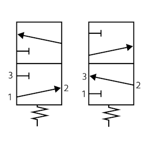
Figure 3: A normally open diagram (left) shows air moving from left to right when unactuated and a normally closed diagram (right) shows air moving from right to left when unactuated.
Types of pneumatic solenoid valves
Pneumatic solenoid valves come in various types, each suited for specific applications. Table 2 shows common types of pneumatic solenoid valves, including 2 position pneumatic solenoid valve diagrams and 3 position pneumatic solenoid valve diagrams.
Table 2: Types of pneumatic solenoid valves and their diagrams
| Valve type | Explanation | Diagram |
| 2/2-way valves | Two ports and two positions. Typically used for simple on/off control of air flow. | 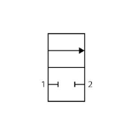 |
| 3/2-way valves | Three ports and two positions. Typically used to control single-acting cylinders. | 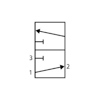 |
| 5/2-way valves | Five ports and two positions. Typically used to control double-acting cylinders. | 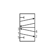 |
| 5/3-way valves | Five ports and three positions, providing more complex control options. | 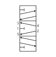 |
Pneumatic solenoid valve applications
Pneumatic solenoid valves are suitable for numerous applications. This section will provide pneumatic solenoid valve circuit diagrams for many applications to help readers understand how different components connect.
Single-acting cylinders
3/2-way directional control valves can operate single-acting pneumatic cylinders. Figure 4 shows a normally closed valve operating with a cylinder. When unactuated, the spring in the cylinder returns it to its original position, and air vents through the valve's exhaust. When actuated, air flows into the cylinder and pushes against the spring force, extending the cylinder's rod.
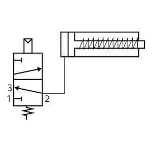
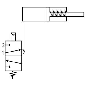
Figure 4: An unactuated 3/2-way pneumatic solenoid valve (NC) connected to a spring-return pneumatic cylinder (left) and its actuated state (right).
Double-acting cylinders
As seen in Figure 5, double-acting cylinders are controlled by 5/2-way valves capable of having air flow and exhaust ports whether the valve is actuated or unactuated. Learn more in our single acting vs double acting pneumatic cylinders article.
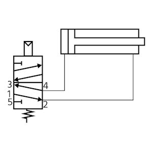
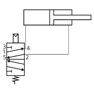
Figure 5: A 5/2-way pneumatic solenoid valve is necessary to control a double-acting pneumatic cylinder.
Speed control
Pneumatic cylinder applications that require precise positioning, smooth operation, or synchronization with other machine components, such as in automated assembly lines, material handling systems, and robotics, may need speed control of the extension and retraction of the piston rod. Figure 6 demonstrates how installing flow control fittings (e.g., needle valves with push-in fittings) between the pneumatic solenoid valve and pneumatic cylinder can accomplish this. Figure 7 demonstrates how installing these needle valve fittings at the valve's exhaust ports can accomplish the same.
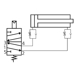
Figure 6: Needle valve fittings installed between valve and pneumatic cylinder provide speed control.
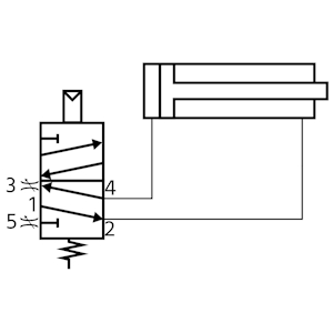
Figure 7: Needle valve fittings installed at the valve's exhaust ports provide speed control for the pneumatic cylinder.
Manual valve for work cylinder and clamp cylinder
Work cylinders and clamp cylinders can be controlled so they work in conjunction with one another. The flow control delays the extension of the work cylinder until the clamp cylinder is properly positioned. The force of the clamp cylinder is restricted to match the load of the work cylinder until the work cylinder is fully extended. When the manual valve is reset, the work cylinder will retract before the clamp cylinder is released.
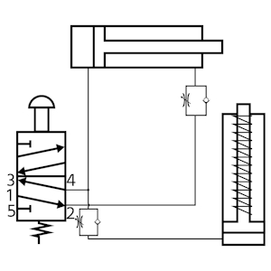
Figure 8: A manual valve actuates a work cylinder (top) and clamp cylinder (right). The throttle valves ensure that the two cylinders extend together and meet.
Cylinder extends and retracts automatically
Using a limit valve (e.g., a pneumatic solenoid valve with a roller or a pneumatic whisker valve) can automatically retract the pneumatic cylinder. As seen in Figure 9, activating the manual valve causes the cylinder to extend, triggering the limit valve, which then resets the manual valve, retracting the cylinder.
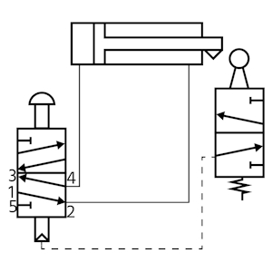
Figure 9: The manual pneumatic solenoid valve extends the pneumatic cylinder, which then interacts with the limit valve (right), causing the manual valve to reset and the cylinder retracts automatically.
Cylinders extend sequentially and retract automatically
Multiple limit valves can be used to set up a sequence of pneumatic cylinders that extend in sequence and then automatically retract when the system is reset. Figure 10 shows how this is accomplished. When manually initiated, this circuit will cause the two cylinders to extend sequentially and then automatically retract, with the manual valve returning to its original position during the process.
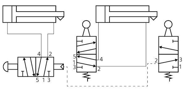
Figure 10: Multiple limit valves allow pneumatic cylinders to extend in sequence and then retract automatically.
Cylinder actuation from two different locations
Figure 11 demonstrates a circuit that uses two manually actuated pneumatic solenoid valves. Although the two valves are in different locations, actuation of either valve will cause the pneumatic cylinder to move to its other position.
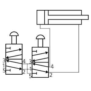
Figure 11: Pneumatic solenoid valves can be in different locations and still actuate the same pneumatic cylinder. Actuating either valve will move the cylinder to its other position.
Cylinder floats at any position
A 5/3-way pneumatic solenoid valve can extend or retract a pneumatic cylinder's piston rod and in its third position (center position) the cylinder does not extend or retract. This means the position of the cylinder can be controlled to float along any point in its path, as seen in Figure 12.
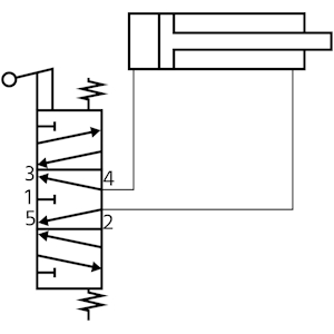
Figure 12: A 5/3-way pneumatic solenoid valve can float the cylinder at any point along its travel by switching to the middle position.
FAQs
What is a pneumatic solenoid valve diagram?
A pneumatic solenoid valve diagram is a schematic representation showing the connections of a solenoid valve used to control air or gas flow.
What is a 2 position pneumatic solenoid valve diagram?
A 2 position pneumatic solenoid valve diagram illustrates a valve with two stable states, showing how the solenoid shifts the valve between these positions to control air flow.


